
ZX80 Core - new ZX80 motherboards
Re: ZX80 Core - new ZX80 motherboards
I have split this topic now to create a new topic for the ZX80NMIX board (link)
Last edited by 1024MAK on Mon Jul 19, 2021 4:06 pm, edited 1 time in total.
Reason: Link added
Reason: Link added
Rich Mellor
RWAP Software
RWAP Adventures
SellMyRetro
Retro-Printer Module
Also Involved in:
Icephorm
RWAP Software
RWAP Adventures
SellMyRetro
Retro-Printer Module
Also Involved in:
Icephorm
Re: ZX80 Core - new ZX80 motherboards
Hi PokeMon, I would still appreciate the kit. I can manage the soldering. I prefer to build everything myself  Is it possible?
Best regards
Martin
Best regards
Martin
Martin
http://www.8bity.cz
http://www.8bity.cz
Re: ZX80 Core - new ZX80 motherboards
HI Martin - which kit? the ZX80Core, or the ZX80NMIX ?
For the uninitiated, the ZX80NMIX is a plug-in board primarily for the ZX80Core to provide a SLOW mode when using the ZX81 ROM.
The ZX80NMIX will also allow other ROMs to run on the ZX80Core, which normally require the NMI circuit on the original ZX81 hardware in order to run.
An example of this is the FORTH H4TH.rom.
The ZX80NMIX board can also be used with the original ZX80 (and potentially clones) if you want to add the NMI circuit - for more details see:
viewtopic.php?f=6&t=1291
Rich Mellor
RWAP Software
RWAP Adventures
SellMyRetro
Retro-Printer Module
Also Involved in:
Icephorm
RWAP Software
RWAP Adventures
SellMyRetro
Retro-Printer Module
Also Involved in:
Icephorm

Re: ZX80 Core - new ZX80 motherboards
It is back !
As the ZX80CORE have been sold out for the last two month there are now available again with some small changes.
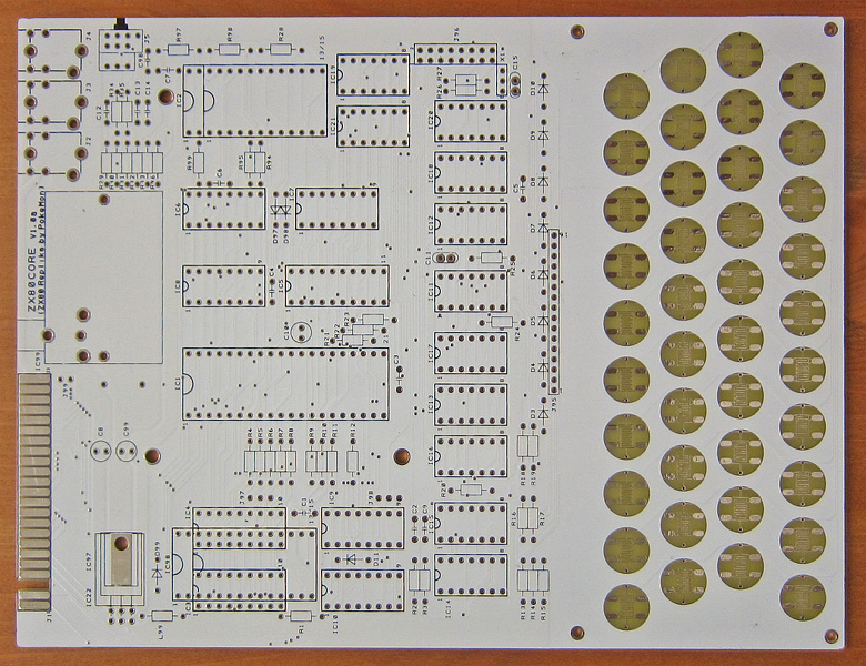
The new revision V11 (2014) has an onboard video circuit, similar to ZX8-CCB and the illumination kit has been revised.
Both parts are build up with SMD components and placed on the backside (solder side).
The SMD components are quite easy to solder with size 1206 (0.12 x 0.06 inches or 3 x 1.5 mm) and placed in 1/10 inch raster (2.54mm).
The blue marked area on the board is the video part, the green marked is the illumination kit.
If somebody is in doubt with his soldering knowledge - the ZX8-CCB can be used as well on J94 instead of SMD components and the illumination kit is not really needed for operation (just a nice gimmick).
All errors on the previous versions have been solved (short of R4, missing resistor on pin 1 of EPROM/EEPROM).
It is now possible to use the full capacity of a 27256 or 27512 EPROM (up to 32/64k) as there is a new jumper J100 which connects A14 (pin 27) of these EPROMs via a resistor to GND (low) which can be switched to high with the ROM switch J5. If an EEPROM is used, the pin 27 can be connected simply with the /WR signal of the CPU to overwrite the EEPROM if wanted.
Unfortunately there is a new error on the board regarding the onboard video when typing the pin-out of IC93 (74LVC125) in my layouting program.
This can be corrected with 2 wires and not soldering pins 9,11,12 but as this is a little bit tricky I decided to do this for every board myself.
So anyone buying the board only gets the driver IC for free.
And the manual has been updated and can be found here for the new version V11 (2014):
http://www.8bit-wiki.de/index.php?id=3& ... /ZX80Core/
The board looks nearly same like before:
and this when finished soldering work
As the ZX80CORE have been sold out for the last two month there are now available again with some small changes.
The new revision V11 (2014) has an onboard video circuit, similar to ZX8-CCB and the illumination kit has been revised.
Both parts are build up with SMD components and placed on the backside (solder side).
The SMD components are quite easy to solder with size 1206 (0.12 x 0.06 inches or 3 x 1.5 mm) and placed in 1/10 inch raster (2.54mm).
- SMD_Video_IKITk.jpg (127.32 KiB) Viewed 5428 times
If somebody is in doubt with his soldering knowledge - the ZX8-CCB can be used as well on J94 instead of SMD components and the illumination kit is not really needed for operation (just a nice gimmick).
All errors on the previous versions have been solved (short of R4, missing resistor on pin 1 of EPROM/EEPROM).
It is now possible to use the full capacity of a 27256 or 27512 EPROM (up to 32/64k) as there is a new jumper J100 which connects A14 (pin 27) of these EPROMs via a resistor to GND (low) which can be switched to high with the ROM switch J5. If an EEPROM is used, the pin 27 can be connected simply with the /WR signal of the CPU to overwrite the EEPROM if wanted.
Unfortunately there is a new error on the board regarding the onboard video when typing the pin-out of IC93 (74LVC125) in my layouting program.
This can be corrected with 2 wires and not soldering pins 9,11,12 but as this is a little bit tricky I decided to do this for every board myself.
So anyone buying the board only gets the driver IC for free.
And the manual has been updated and can be found here for the new version V11 (2014):
http://www.8bit-wiki.de/index.php?id=3& ... /ZX80Core/
The board looks nearly same like before:
and this when finished soldering work
- IMG_6383kk.jpg (90.48 KiB) Viewed 5428 times

Re: ZX80 Core - new ZX80 motherboards
I took the plunge and ordered a kit. Thank you Pokemon for making a second run. I have always found out about someone's ZX80/81 replica motherboards too late and I felt I missed out on this one too. I have some plans for it. One is to possibly replace the 5V regulator with a Low Dropout voltage regulator so it can run at 6V rather than 9v. I also have some 5 AA battery holders so I may be able to make it portable.
Another thing is I have an idea for a case. I have a friend who has a high quality 3D printer and a laser cutting table. I was thinking of designing a case that is similar in shape to the ZX80 but with a flat top made of clear acrylic so I can show off the board and the LEDs . I also have thought up a way to sandwich card stock and a plastic sheet to put above the smd tactile switches (FYI the alps switches are available in the US at Mouser for 55 cents each in lots of 50). That way you can easily change the keyboard layout. Once I get this worked out I'll post pictures and the design files.
I do have one question. I never have done smd soldering and I don't have much in the way of a workshop. The videos I watch say you must have a solder station with variable temperature. I only have a 15/30 watt solder iron and will be using small diameter lead core solder. Is this ok to use and at which wattage?
Another thing is I have an idea for a case. I have a friend who has a high quality 3D printer and a laser cutting table. I was thinking of designing a case that is similar in shape to the ZX80 but with a flat top made of clear acrylic so I can show off the board and the LEDs
I do have one question. I never have done smd soldering and I don't have much in the way of a workshop. The videos I watch say you must have a solder station with variable temperature. I only have a 15/30 watt solder iron and will be using small diameter lead core solder. Is this ok to use and at which wattage?
2X Timex Sinclair 1000, ZX81, ZX80Core, 5X 16K Ram Pack, ZXBlast, ZX P file to Ear Input Signal Converter, Elf II
Re: ZX80 Core - new ZX80 motherboards
Sorry for late answer - you could even solder the SMD parts with a normal solder iron - they are quite big and there is not much difference if you solder an IC or socket or resistor or a SMD resistor or capacitor. You should use a small solder tip - the smallest you can get. I would use maximum 1.0 mm, better 0.8 mm for the small transistors. I did use a cheap soldering station ago and you can get adjustable temperature for about 10 EUR or 15 USD I think. You don't need an electronic temperature control if not often used.
Sounds funny using batteries for the ZX80 - but I think they wouldn't run very long as it consumpts about 400mA.
Sounds funny using batteries for the ZX80 - but I think they wouldn't run very long as it consumpts about 400mA.
Re: ZX80 Core - new ZX80 motherboards
Thanks for the advice. I may have access to that friend's, that I mention, workshop next weekend and he does SMD work. I know I won't get it all done there and I don't get to his place to often so I'll be doing some SMD work with my cheap soldering iron.
Yes you are right about batteries. They probably last at best 3 hours. I saw 2 articles that made me think about batteries. One was about using them on a ZX80 as a "UPS" for momentary power brownouts. The other was a wheeled robot driven by a ZX81 but I believe in that article the robot was tethered to a power outlet.
Yes you are right about batteries. They probably last at best 3 hours. I saw 2 articles that made me think about batteries. One was about using them on a ZX80 as a "UPS" for momentary power brownouts. The other was a wheeled robot driven by a ZX81 but I believe in that article the robot was tethered to a power outlet.
2X Timex Sinclair 1000, ZX81, ZX80Core, 5X 16K Ram Pack, ZXBlast, ZX P file to Ear Input Signal Converter, Elf II
-
1024MAK

- Posts: 5529
- Joined: Mon Sep 26, 2011 10:56 am
- Location: Looking forward to summer in Somerset, UK...
- Contact:
Re: ZX80 Core - new ZX80 motherboards
The current consumption depends on the type of chips fitted. If CMOS logic chips (74HCTxx), a CMOS CPU, and CMOS memory chips are used, complete with a switching regulator, battery operation is viable.
If however 74LSxx logic, a NMOS CPU, NMOS EPROM and the old SRAM chips are used, the very high current consumption will mean that using batteries is not very practical.
Mark
If however 74LSxx logic, a NMOS CPU, NMOS EPROM and the old SRAM chips are used, the very high current consumption will mean that using batteries is not very practical.
Mark
ZX81 Variations
ZX81 Chip Pin-outs
ZX81 Video Transistor Amp
 Standby alert
There are four lights!
Step up to red alert. Sir, are you absolutely sure? It does mean changing the bulb
Spring approaching...
ZX81 Chip Pin-outs
ZX81 Video Transistor Amp
There are four lights!
Step up to red alert. Sir, are you absolutely sure? It does mean changing the bulb
Spring approaching...
Re: ZX80 Core - new ZX80 motherboards
Yes - when talking about the ZX80CORE with HCT chips and 6264 or 62256 SRAM and 28C256 EEPROM the current drops below 100mA.
Re: ZX80 Core - new ZX80 motherboards
Pokemon,
Is there any modifications I need to make to the Z8-CCB circuitry on the ZX80 Core to work with NTSC TVs or can it work with an AV (Audio/Video) input without modification? I have 3 TVs that accept AV and 2 AV to UHF 3/4 converters that I can use on one of my older non-AV TVs so I hope AV works.
Is there any modifications I need to make to the Z8-CCB circuitry on the ZX80 Core to work with NTSC TVs or can it work with an AV (Audio/Video) input without modification? I have 3 TVs that accept AV and 2 AV to UHF 3/4 converters that I can use on one of my older non-AV TVs so I hope AV works.
2X Timex Sinclair 1000, ZX81, ZX80Core, 5X 16K Ram Pack, ZXBlast, ZX P file to Ear Input Signal Converter, Elf II