The trace running just below C10 seems to have a manufacturing fault in that it's broken and shorted to the positive leg of C10 itself. This would explain the odd reset behaviour...
Now, next step is to fix it Would anyone have the best advice as to how to fix it? I'm used to repairing broken tracks on non-masked boards such as the ZX81/Spectrum, but haven't tried one of these before...
As the tracks on the ZX80CORE boards are very fine, I would suggest that you replace the trace by running a thin insulated wire to completely by-pass the trace on the underside of the board. Ideally run it from a pad to a pad, if not use a via.
Mark
PS If you cannot work out where it runs, I can have a look at my (still) unpopulated board tomorrow.
PPS Don't forget to cut the shorted part of the track with a sharp knife
Ok, short to C10 cut and, given that the errant trace is the D7 line, it looks like the termination point for the trace is the left side of R9. So one very quick patch wire later....
It's Alive.....!
More debugging tomorrow (haven't checked the keyboard nor entered a program yet), a celebratory G&T is in order tonight
Thank you Mark and Pokemon, you've both been of massive help!
Just two - first between /CLK and GND on the edge connector, and then the malformed track routing D7 to C10.
To be fair, PokeMon does advise that the tinned portions of the board be inspected thoroughly for shorts. I just forgot to check the edge connector for about a day or so
The malformed track issue seems to me to be a complete fluke, I've just been very unlucky I would imagine. However looking back, I've learned much more about the workings of the ZX80 this way. It's no fun if it's easy, right?
Of course, I am not interested in machines that work at first try!
Said this, I do not like these opaque soldering mask. I prefer the transparent ones.
balford wrote:The malformed track issue seems to me to be a complete fluke, I've just been very unlucky I would imagine. However looking back, I've learned much more about the workings of the ZX80 this way. It's no fun if it's easy, right?
B
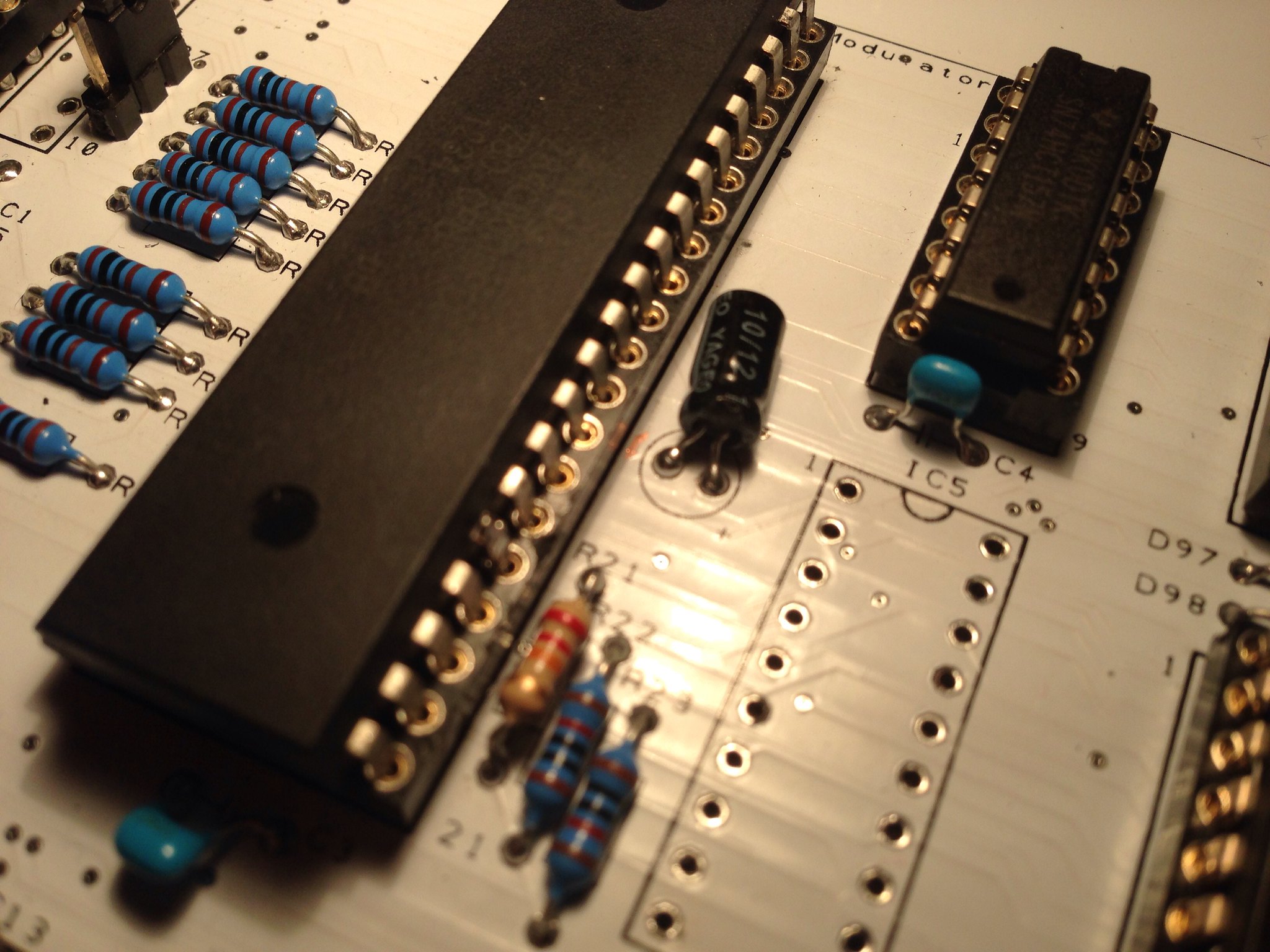
Well I am surprised as well - and I think I can view in on your picture you posted.
It seems to be a small short on the top layer between the wire (marked red/blue in the attached picture) and the right (+) pin of C10 (reset line).
I am not sure how this could happen as it is covered with white paint.
Maybe a failure when the boards have been exposured and acid-treated after.
I am glad you found it and your board is hopefully working now.


