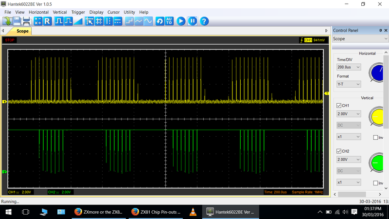
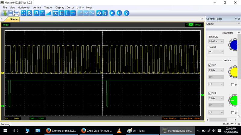
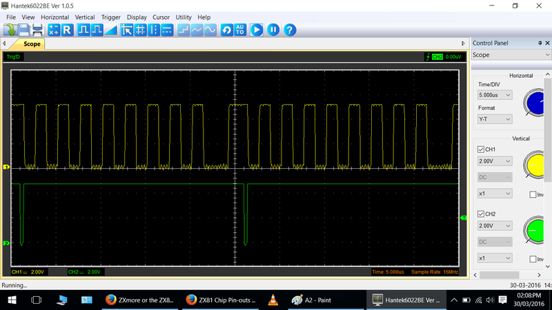
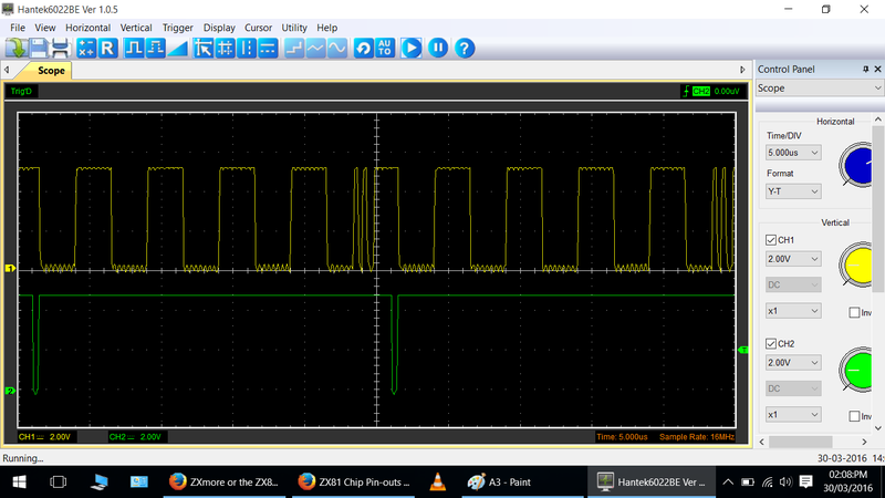
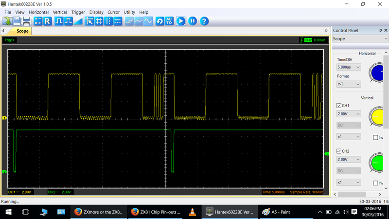
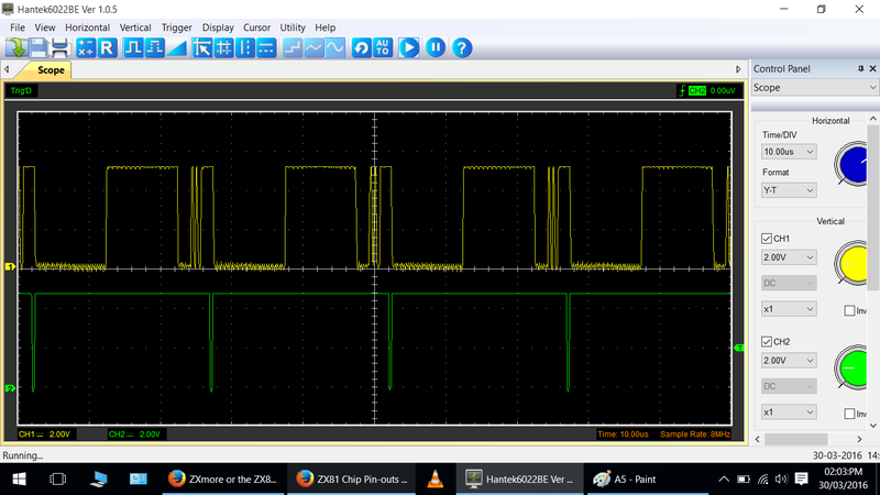
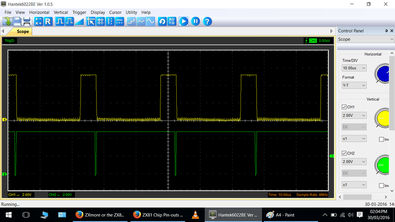
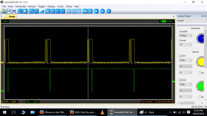
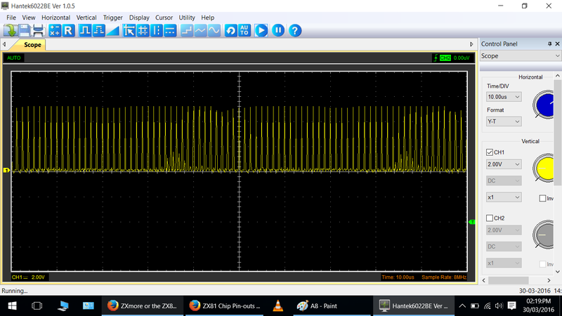
So here is a new diagnostic ROM which allows to test RAM access on a scope level (with an oscilloscope to follow signals).
This is burned into instance 3 while the ROM test code is still in instance 2 accessible.
The ROM code is available in this ZIP for standalone programming into the flash in a specific instance for interest as well as source code.
It is not too much.
Next drag rom 4 will then be a step-by-step utility with further functions to follow even with the LEDs and/or pattern on TV.
But back to this version, here is the code:
Code: Select all
format zx81 as 'rom'

define  NEWLINE         $76

define  IOANY           $FF     // "any" io address
define  IOADRKBD        $FE     // io address, keyboard check
define  IOADRNMION      $FE     // io address, NMI on
define  IOADRNMIOFF     $FD     // io address, NMI off
define  IOADRBASE       $F4     // io base address
define  LATINT          0       // offset for io address LATINT (special functions)
define  LATROM          1       // offset for io address LATROM (rom latch)
define  LATRAM          2       // offset for io address LATRAM (ram latch)
define  LATUSB          3       // offset for io address LATUSB (usb communication)
define  IOADRLATINT     $F4     // io address, internal mysterious latch
define  IOADRLATROM     $F5     // io address, ROM latch and control signals
define  IOADRLATRAM     $F6     // io address, RAM latch and memory configuration

        ORG     $0

        OUT     (IOADRNMIOFF),A
        DI
        IM      1
        LD      HL,0
        LD      SP,HL
        LD      IX,main
        JR      start
        db      38h-$ dup(NEWLINE)
rst38:
        POP     DE
        OUT     (IOANY),A
        JR      main
start:
        LD      HL,$3FFF
        LD      BC,$0010
        JP      (IX)
pre:
        LD      A,$FF
        LD      R,A
        EI
main:
        XOR     A
        INC     HL
        LD      (HL),A
        SCF
        RL      (HL)
        RL      (HL)
        RL      (HL)
        RL      (HL)
        RL      (HL)
        RL      (HL)
        RL      (HL)
        RL      (HL)
        RL      (HL)
        JR      NC,bad
        OR      (HL)
        JR      NZ,bad
        IN      A,(IOADRKBD)
        RRCA
        JR      NC,vidon
        DJNZ    main
        DEC     C
        JR      Z,start
        JP      (IX)
vidon:
        LD      IX,pre
        JP      (IX)
bad:
        LD      A,L
        OUT     ($FF),A
        LD      A,H
        OUT     ($FF),A
        LD      B,32
        DJNZ    $
        JR      bad

        db      2000h-$ dup(NEWLINE)
So this utility will test the RAM continuously and test the first 4k window of RAM which is enough to startup ZXmore ($4000-$4FFF). The ram test shifts a bit through every memory cell from bit 0 to 7 and tests if it is not lost after 9 rotate operations with RL (HL). This is done in 256 byte packages, repeated 16 times and repeats from beginning. There is a keyboard scan included which changes the ram test procedure when a key in column 0 (e.g. shift) is pressed and executes some interrupts to test some further action.
If any bad RAM address in this range is found it loops in the bad section, showing just 2 short IORQ pulses repeated regularly and giving the tested address on A8-A15 which can be measured out with the scope. First L is shown (lower address part), after H is shown on the second pulse (higher address part).
First part (after power-up in instance 3 with no key pressed):
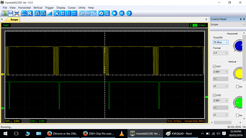
IORQ (pin 20 of cpu) should be used as trigger signal and a second signal measured (triggering on falling edge).
IORQ one pulse every 33us with 400ns width (low pulse)
HALT, NMI high (no pulse)
WR with 10 low pulses between two IORQ pulses, nearly in the middle
A15, A13, A12 low (no pulse)
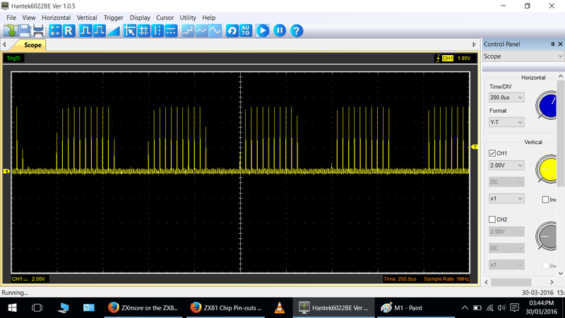
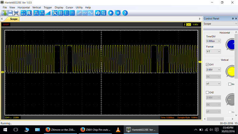
A14 with 11 high pulses between two IORQ pulses, the first and last half width of the other 9 pulses
A11 same as A14 but fast blinking, not steady
A10 same as A11 but blinking with double speed
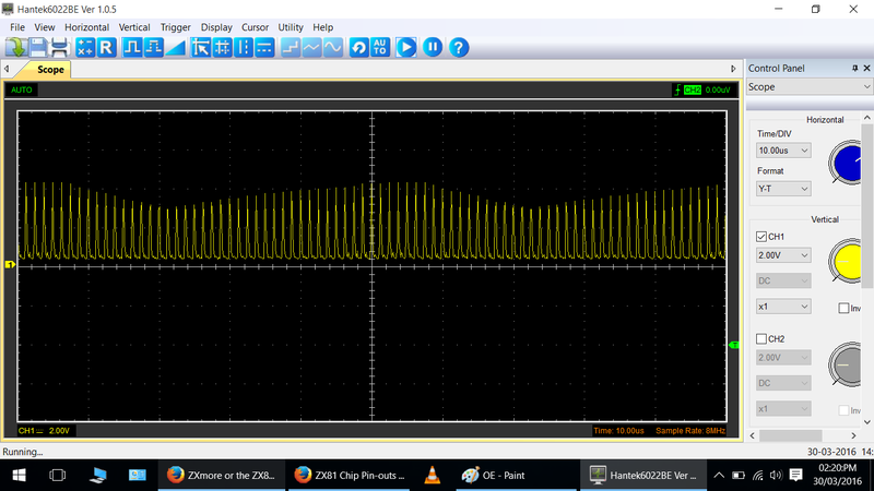
A9 same as A11 but blinking with quadruple speed
A8 same as A11 but maybe blinking too fast to see it blinking (8 times speed)
RAMCS (pin 22 of RAM, IC3) with one single pulse, 9 double pulses, one single pulse (repeating)
Second part (when shift key is pressed shortly):
The clk frequency changes from 6.5 MHz to 3.25 MHz as this code is interpreted to be video code (VIDON goes high, pin 11 of IC6) while it does not show a recognizable picture. So the above signals are still present with half frequency (IORQ pulse every 66us with 800ns width).
Additionally the following signals should be present:
Change trigger signal to A15 (pin 5 of cpu) with triggering on positive edge.
A15, A13, A12 two high pulses with 2us width directly followed, repeated every 16.6ms (maybe seen as one pulse depending on resolution)
VSYNC (pin 10 of IC11) - one high pulse repeated every 16.6ms, pulse width 60us, directly after the two single pulses on A12-A15
If these signals can be measured the access to the RAM should be working, also interrupts (INT) and keyboard IO.
This is for investigating deeper problems with an oscilloscope.
