ZX81+35 Clone

Discussions about Sinclair ZX80 and ZX81 Hardware
User avatar
RetroTechie
Posts: 379
Joined: Tue Nov 01, 2011 12:16 am
Location: Hengelo, NL
Contact:

Re: ZX81 Clone

Post by RetroTechie »

Excellent progress so far, mahjongg! 8-)

For the tape input, I found that the ZX81 needs to see a "0" regularly for tape loading (and BREAK!) to work normal. Pick DC resting voltage too low, and you need too large a voltage swing to obtain regular 0<->1 transitions. Pick DC resting voltage too high, and input may see continuous "1" (or "0" occurring too rarely).

The series resistor serves to limit input current when (for whatever reason) voltage spikes occur on the input. Don't be afraid to bump up those resistor values! It'll help to lower required value for series capacitor, and perhaps also reduce sensitivity to static discharges etc. Also it'll maximise the voltage swing, which is something you very, very much need when signal comes from a headphone output. ;) Input "clamping" diodes aren't needed as they are included in 74HC inputs.

With resistor values picked, series capacitor value then determines cut-off frequency. I would pick that comfortably low such that for normal tape loading operation, the C's series impedance doesn't come into play. Say <20 Hz or so?

With signals going into a 74HC541, may I suggest: D9 & D15 removed, R58 = 22k, R70 = 56k, R59 = 1k Ohm, and C8 = 470 nF. That should get you pretty close to a usable circuit.
User avatar
PokeMon
Posts: 2264
Joined: Sat Sep 17, 2011 6:48 pm

Re: ZX81 Clone

Post by PokeMon »

Mahjongg,

you are right about the simple designs. In my ZX80Core schematic I used 47nF and 2k2 resistor which works quite good for a LS TTL input (74LS365) but found out it is less sensitive when using 74HCT365. So in a modified design I used just a 10k pull down resistor on the HCT365 and let the 47nF capacitor (no pullup resistor and no diodes of course). Anyway you need a significant voltage level at the input - I think I needed about 3.5 to 4Vss which gives about 2Vss positive to trigger the input correctly. My PC sound card reached this level while my new Mac mini doesn't reach it anymore. :?

So amplification is not a bad idea in general but has to be measured out properly depending on the logic you use when you keep it simple. I would propose following setup with your inbuilt transistor:

Just tie the base to +5V with 47k and to GND with 10k to give it a slight kick to be switched in default state (should give around 0.85V - enough to switch) and let the signal do the rest. I think this should give nearly the same pulses and assure that it is low during pause. I would let the 10uF capacitor from your original design. It should give the same amount of pulses, the same signal/pause ration just 150us moved the beginning. So a try worth. Maybe you have to adjust resistor values slightly, so using a 50k potentiometer wouldn't be a bad idea instead of 47k fixed resistor. I would also decrease the series resistor from the signal to 220R - something like that. 1k would cut 10% of your signal level (to 10k pulldown) where every percent counts.

I think the Sinclair architects (or should better say artists :mrgreen: ) did the input circuit in a simple experimental way.
User avatar
mahjongg
Posts: 181
Joined: Tue Nov 24, 2015 10:25 pm

Re: ZX81 Clone

Post by mahjongg »

So, I remembered having seen that on a very bad copy of the TS1500 (the official US ZX81 clone) schematic that it's cassette input also used a transistor, so I looked it up. The schematic was very nearly unreadable, but I was still able to get the idea it used, even though the values of capacitors and resistors it used were nearly unreadable, at least not with 100% certainty, I could guess many of them, but not the the values of C1 and R2.
It did remind me of the initial transistor schematic I had, but with some important changes, specifically the pullup resistor, that generates the base bias, and the 220 Ohm emitter resistor.
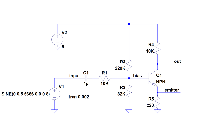
So I made an LTSPICE simulation schematic, and discovered that with the right components it really did work well.
This is the setup with the optimized values I came up with:
Image
and this is a printout of the simulated waveforms:
Image
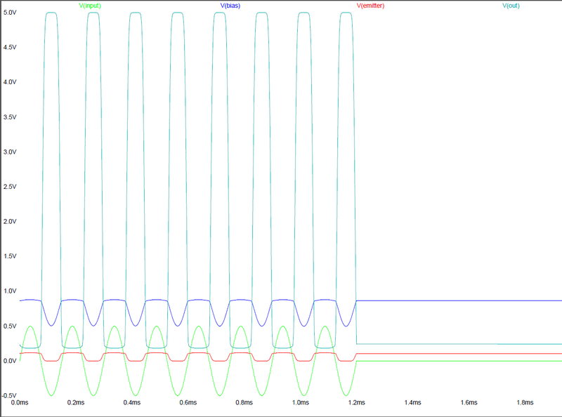
Looks good doesn't it? The green signal is the input signal, and the blue-grey signal is the generated output signal.
I did some more testing after I made these pictures, and discovered a few more things:
I propose to increase C1 to 10uF, as after a long period of bursts otherwise the output does not transfer immediately to 0V, but stays for time time in the dangerous zone above 1V. This is especially true for capacitance's of say 100nF. Less essential, but still better would be to add a resistor of about 1K over the input to GND, it also has an influence on the behavior of the output going to GND after a burst of pulses.
As you can see the negative going pulse drives the output high, not the positive one, but that does not matter, like you said it only causes a 150µS delay. This design works well with inputs of about 1V peak/peak. It also works with smaller signals, but then (for a sinusoidal signal) the generated OUTPUT pulse wide changes, somewhat. Higher input signals are better. R5 helps to get high pulses on the output that have an almost 50% duty cycle, so its definitely an improvement over leaving it out. The correct value of R2 is essential for the correct operation of the circuit, as it sets the bias voltage right, changing it too much influences the circuit, and means it either does not work at all, or operates only with larger input signals.

I think that with this input circuit the ZX81 cassette input will improve dramatically, and work with HCT logic. It also protects against ESD impulses.
The only further improvement I foresee is a very small capacitor over the 1K input termination resistor, which would filter off unwanted HF signals which could cause spurious pulses. But I must see if I can find space in my design to add one.
User avatar
PokeMon
Posts: 2264
Joined: Sat Sep 17, 2011 6:48 pm

Re: ZX81 Clone

Post by PokeMon »

Yes, good work from you. 8-)
User avatar
Paul
Posts: 1604
Joined: Thu May 27, 2010 8:15 am
Location: Germanys west end

Re: ZX81 Clone

Post by Paul »

mahjongg wrote:So, I remembered having seen that on a very bad copy of the TS1500 (the official US ZX81 clone) schematic that it's cassette input also used a transistor, so I looked it up.
Maybe you had better looked into Dick Berrys redrawn TS1500 schematic.pdf?
Attachments
TS-1500 Schematic.pdf
(135.72 KiB) Downloaded 239 times
In theory, there is no difference between theory and practice. But, in practice, there is.
User avatar
mahjongg
Posts: 181
Joined: Tue Nov 24, 2015 10:25 pm

Re: ZX81 Clone

Post by mahjongg »

Paul wrote:
mahjongg wrote:So, I remembered having seen that on a very bad copy of the TS1500 (the official US ZX81 clone) schematic that it's cassette input also used a transistor, so I looked it up.
Maybe you had better looked into Dick Berrys redrawn TS1500 schematic.pdf?
well shoot! let me tell you that I have searched for another schematic of the TS1500 for over an hour, and I did not find this one, perhaps I shouldn't have fixated so much on pictures of it.

what kind of source did Dick have? Perhaps the same schematic I found (several times I might add), this one?
Image
i'm asking because the values for C19 (47pF), and R21 (18K) are quite improbable, 47uF is more likely than 47pF, these (or similar) were however values I tried to plug into SPICE, as I could guess them when looking at the original schematic. In fact I could only guess that C19 was a very small value, (0.000something like) and I guess I thought I saw 8K2 for R21, so I tried 100pF and 8K2, but the result was dramatically bad. such a low value for C19 would mean that only the flank of a very fast falling input would generate a very narrow pulse, and 8K2 (and probably also 18K) would close Q1 so much that in between pulses the output would be high. note that C13 (47nF) is a factor 1000 larger than C19 (47pF), so fast falling flanks on the input are improbable, they would be shorted to ground.

The values I found, I found by experimenting with the values and tweaking them until I got a working circuit.
still its possible that with C19 = 47pF, and R21 = 18K and R22 = 4K7 somehow the circuit could work, tomorrow I'm planning to build up the circuit with PTH components on a small perfboard, so it is easy to modify. I will also try with the values found in Dick Berry's redraw, just because I'm curious if that will work, but I don't expect it.

p.s. I have looked at several pictures of TS1500 PCB's, to look for C19, and to my amazement C19 either looked like a resistor, or as a very small brown capacitor, not like the expected elco, that makes me wonder! The ZX80 used 47nF, and the ZX81 even 10nF, but both controlled LS logic. we will find out what works best. reading the bad schematic again, and looking at the ring colors (yellow purple black gold), it could be either 0.0047 or "47" but is it pF or nF? or perhaps 4.7nF? 47 pF seems so improbable, still i will find out what works best with my clone.
User avatar
mahjongg
Posts: 181
Joined: Tue Nov 24, 2015 10:25 pm

Re: ZX81 Clone

Post by mahjongg »

Success!

With my original interface (with the addition of a 1K terminating resistor, in parallel with an 47pF capacitor, for DC restoration, and HF filtering) it worked, after I set the audio level halfway, and I played PokeMons .wav file!

evidence:
Image
Image

Will try what happens when I chance C1 to 47 pF, and R2 to 18K.
User avatar
mahjongg
Posts: 181
Joined: Tue Nov 24, 2015 10:25 pm

Re: ZX81 Clone

Post by mahjongg »

Nope! With a 47 PF, and 18K resistor it did not work at all!

In fact, like I said, with 18K pull-down instead of 82K the moment you start the

Code: Select all

LOAD ""
command the screen turns black, indicating the ZX81 sees a permanent high on its input, and no amount of signal changed that.
I also tried without the 22K I mounted in parallel with my 82K to get an 18K combination, so with just the 47pF, but the capacitor was clearly simply too small to let any signal through.

I also tried 47nF, and that worked, it even worked not only with medium, but also at the loudest setting, I guess what the ZX81 "sees" is a much narrow pulse for each pulse that is generated, but that still works.

Still I have a bit more trust in my 10uF value.

funny thing, I would not have believed, but loading a file even works when running at 6.5 MHz (with my turbo enabled).


All that said, the only thing I succeeded in loading till now is PokeMon's .WAV file, files played from a .P file with WINTZX did not load at all, not surprising because the player was designed to create sounds suitable for the spectrum, not for the ZX81.

both the links given by sir morris lead to either non existing files, or damaged .zip files.

If found a few file converters that converted ZX81 .P files to audio files, but they all produced .RAW files which my audio players could not accept .

so I'm still looking for a suitable player that converts a .P file directly to sound, or (less preferred) to a .wav that is compatible with VLC.
Last edited by mahjongg on Sat Mar 26, 2016 10:31 pm, edited 1 time in total.
User avatar
1024MAK
Posts: 5534
Joined: Mon Sep 26, 2011 10:56 am
Location: Looking forward to summer in Somerset, UK...
Contact:

Re: ZX81 Clone

Post by 1024MAK »

Alas, a lot of the older attachments on this forum were lost due to a failure some years ago :(
It's very annoying :twisted:

Mark
ZX81 Variations
ZX81 Chip Pin-outs
ZX81 Video Transistor Amp

:!: Standby alert :!:
There are four lights!
Step up to red alert. Sir, are you absolutely sure? It does mean changing the bulb :!:
Spring approaching...
User avatar
PokeMon
Posts: 2264
Joined: Sat Sep 17, 2011 6:48 pm

Re: ZX81 Clone

Post by PokeMon »

First, congratulations to your success ! 8-)
mahjongg wrote: funny thing, I would not have believed, but loading a file even works when running at 6.5 MHz (with my turbo enabled).
I don't think it is loading with 6.5 MHz. LOAD and SAVE operate in FAST mode only and switch off NMI which switch off your turbo for the duration of LOAD or SAVE.

For creating WAVs I can point you to the ZX-IDE which is for development purposes with mixed BASIC/Assembly for ZX81 but has facilities to transfer files directly via the sound card or create WAVs. This may not be very convenient depending on your desires but a first start to create WAVs. I may take a look later on my hard disk where I have some tools which are working as well and allow command line operation. The ZX-IDE is a WIN 32 bit application but should work with WINE on Linux and or OS X as well.

http://sinclairzxworld.com/viewtopic.php?f=6&t=1064

So I will come back later with some other tools.
PS: I am not sure if FAST loading will give success, depending on exact clock frequency but worth a try. It speeds up and is a two stage loader and will create one single WAV file. Also read the instructions for audio transfer. I think I did not have much success with VLC player controlled directly.
Post Reply