

OK, good point. Messing with the card edge connector with the power on would certainly do it. It probably wouldn't do the CPU any good either.
Another busted Zeddie
Re: Another busted Zeddie
Re: Another busted Zeddie
Well, I have taken the ROM off the board, desoldered the wires, bent the legs straight and popped into my EPROM reader.
I set it up as a generic 2764 and got FF from all addresses.
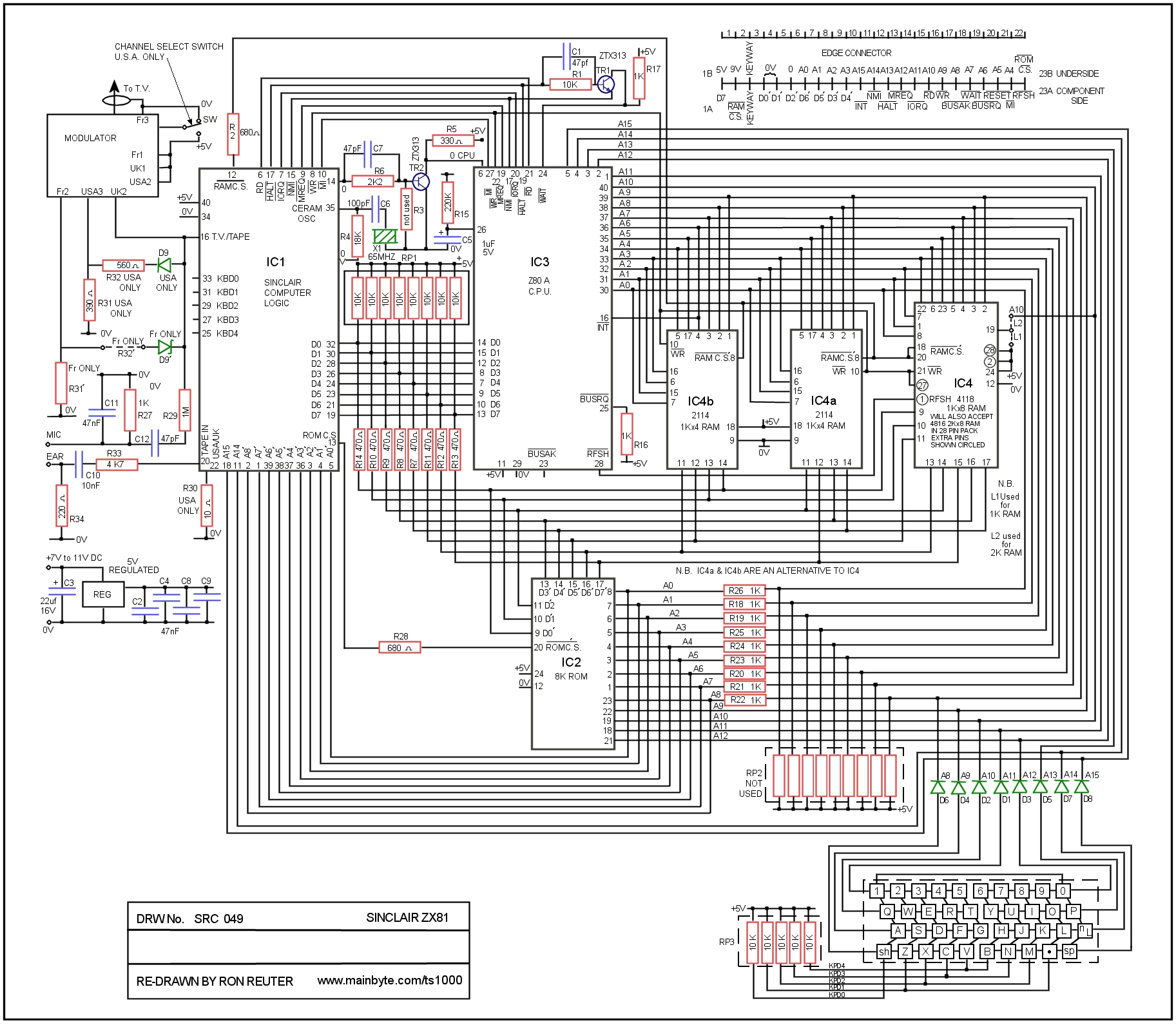
On the other hand its pinout (as defined by the circuit diagram I found here http://www.mainbyte.com/ts1000/good_schematic_hi.jpg) doesn't match a standard 2764. Searching for its code returns nothing and I just realised it's a datae code anyway (8301, duhh).
But it appears to be (after a bit more googling) a Motorola MCM68764 which isn't supported by my reader - darn it! The only other option I have here is to pull out my enormous S100 system which has a variety of EPROM programmer boards (none currently fitted but we will see...)
Alas the poor old Zicon goes back in its box.
Edit: The S100 box can't read the 68764 EPROM despite having 3 different PROM cards.. They are all Intel PROM devices, seemingly (though I did find something that could read / write the TMS2716 weirdo ROM used in the Superbrain but nothing for the 68764.. Darn it.
I set it up as a generic 2764 and got FF from all addresses.
On the other hand its pinout (as defined by the circuit diagram I found here http://www.mainbyte.com/ts1000/good_schematic_hi.jpg) doesn't match a standard 2764. Searching for its code returns nothing and I just realised it's a datae code anyway (8301, duhh).
But it appears to be (after a bit more googling) a Motorola MCM68764 which isn't supported by my reader - darn it! The only other option I have here is to pull out my enormous S100 system which has a variety of EPROM programmer boards (none currently fitted but we will see...)
Alas the poor old Zicon goes back in its box.
Edit: The S100 box can't read the 68764 EPROM despite having 3 different PROM cards.. They are all Intel PROM devices, seemingly (though I did find something that could read / write the TMS2716 weirdo ROM used in the Superbrain but nothing for the 68764.. Darn it.
Last edited by JonB on Wed Nov 17, 2021 4:26 pm, edited 2 times in total.
-
1024MAK

- Posts: 5118
- Joined: Mon Sep 26, 2011 10:56 am
- Location: Looking forward to summer in Somerset, UK...
Re: Another busted Zeddie
A 2764, 27C64, 27128 or 27C128 EPROM can be used. The pin-out of these EPROMs is however slightly different to that of the socket.
Moggy may post details before I get a chance to. The details are on the forums, but finding them is slightly tricky…
Mark
Moggy may post details before I get a chance to. The details are on the forums, but finding them is slightly tricky…
Mark
ZX81 Variations
ZX81 Chip Pin-outs
ZX81 Video Transistor Buffer Amp
 Standby alert
There are four lights!
Step up to red alert. Sir, are you absolutely sure? It does mean changing the bulb
Looking forward to summer later in the year.
ZX81 Chip Pin-outs
ZX81 Video Transistor Buffer Amp
There are four lights!
Step up to red alert. Sir, are you absolutely sure? It does mean changing the bulb
Looking forward to summer later in the year.
Re: Another busted Zeddie
Thanks Mark happy to help.
2764s' are my chip of choice and and the only one I'm familiar with, I believe the 27128s are almost impossible to obtain whereas the 2764 27c64 are more readily obtainable.
I used to use a convoluted wiring method on the 2764 EPROMs' so as to act like the original but a fellow forum member showed me the light that only two pins need lifting and 2 wires soldered as per the picture.
It seems Sinclair may have had the 2764 in mind as the connections needed to emulate the original ROM are already on the board and this simpler method is all that is required.
- Attachments
-
- 20200622_094743.jpg (48.13 KiB) Viewed 1313 times
-
1024MAK
- Posts: 5118
- Joined: Mon Sep 26, 2011 10:56 am
- Location: Looking forward to summer in Somerset, UK...
Re: Another busted Zeddie
As per what Moggy posted 
If you want more details, trundle over to here
ROM version info here.
Sinclair ROM images here.
We like the much improved (unofficial) better (faster) ZX81X2 Big Bang ROM (see here).
Mark
Tags EPROM 2764
If you want more details, trundle over to here
ROM version info here.
Sinclair ROM images here.
We like the much improved (unofficial) better (faster) ZX81X2 Big Bang ROM (see here).
Mark
Tags EPROM 2764
ZX81 Variations
ZX81 Chip Pin-outs
ZX81 Video Transistor Buffer Amp
Standby alert
There are four lights!
Step up to red alert. Sir, are you absolutely sure? It does mean changing the bulb
Looking forward to summer later in the year.
ZX81 Chip Pin-outs
ZX81 Video Transistor Buffer Amp
There are four lights!
Step up to red alert. Sir, are you absolutely sure? It does mean changing the bulb
Looking forward to summer later in the year.
Re: Another busted Zeddie
Wow thanks guys that's exactly the info I need.
How on earth does the wiring thing work? Pin 1 of a 2764 is Vpp (so shouldn't be connected here, or rather wouldn't have an effect) but the ZX81 schematic shows it as A7. In other words, connecting A7 to the 2764's Vpp pin would mean the ROM wouldn't be readable, unless it is sited somewhere else in the ROM's space?
Obviously, I will have to analyse it a bit better...
-
1024MAK
- Posts: 5118
- Joined: Mon Sep 26, 2011 10:56 am
- Location: Looking forward to summer in Somerset, UK...
Re: Another busted Zeddie
A 24 pin mask ROM does not fit in the socket with pin 1 of the ROM being connected to pin 1 of the socket (most boards have either a 28 pin socket or have a ROM soldered in the bottom part of the 28 pin layout).
Look at the pin-out diagram in one of the links that I provided.
Mark
Look at the pin-out diagram in one of the links that I provided.
Mark
ZX81 Variations
ZX81 Chip Pin-outs
ZX81 Video Transistor Buffer Amp
Standby alert
There are four lights!
Step up to red alert. Sir, are you absolutely sure? It does mean changing the bulb
Looking forward to summer later in the year.
ZX81 Chip Pin-outs
ZX81 Video Transistor Buffer Amp
There are four lights!
Step up to red alert. Sir, are you absolutely sure? It does mean changing the bulb
Looking forward to summer later in the year.
Re: Another busted Zeddie
To reinforce what Marks says, don't confuse pin 1 of the 24 pin original chip with pin1 of the 28 hole socket.
Pins 1 27 28 need to be held at 5 volts and the old way of wiring the 2764 involved linking a wire from pin 1 to 26 27 28.
Pin 26 which is not internally connected on the chip could be left in situ as it was assumed,incorrectly, to be the only 5 volt source on the board to feed the other three pins, however thanks to the aforementioned forum member (rmzalbars' ) correction it's not necessary as the board has 5 volts appearing at all of the above pins as Marks linked to diagrams clearly show. Pin 2 was also lifted and a soldered link wire to lifted pin 23s' socket hole was thought needed to get A12 onto pin 2 of the 2764 when in fact the board connection is already there so these extra wires are not required.
The two pin lifts and two wire additions in the corrected version are just an address line swap and a ground link with the board doing the rest.
It works and works well trust me so don't get bogged down with schematics, and in further agreement with Mark the Big Bang ROM is faster graphically and in some cases mathematically so is the one to use if only because it's got rid of the annoying screen flicker when using the PAUSE command.