Page 1 of 1
You’re gonna need a bigger switch!
Posted: Thu Apr 15, 2021 8:23 pm
by Lardo Boffin
I went to fit another ROMel with multi-ROMs to my zeddy and came to the conclusion the current switch is just too fiddly! I managed to do one a year or two ago but frankly have no idea how I managed it last time.
The switch:
Zeddy for scale:
Can anyone tell me what kind of larger (but not ridiculous large please) switch I can use in its place please?
The current switch is 11mm across and the space where the four wires go is about 6mm across.
My eye sight and sanity thank you in advance.

Re: You’re gonna need a bigger switch!
Posted: Thu Apr 15, 2021 8:36 pm
by 1024MAK
I’m confused

Do you want a more user friendly selection switch? Do you want it to be PCB mounting or panel (case) mounting?
Does it have to be a DIP type switch, or would a rotary selector switch do?
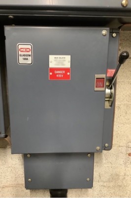
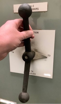
Or are you really wanting me to post a photo of a large switch that would make a Zeddy look rather small...


- Big switch #1

- Big switch #2
Mark
Re: You’re gonna need a bigger switch!
Posted: Thu Apr 15, 2021 9:26 pm
by Lardo Boffin
Blimey! You have a very large switch sir!
I want a switch that will do the same job as the existing one but is physically larger so I can actually solder it. It will be living in my rebuilt zeddy case so it would be cool if it could be mounted somehow to make it accessible without dismantling the case.
I think a rotary one (presumably similar to the ones Retroclinic fits on Masters with switchable OS) would probably be too large.
Am happy to cut a slot in the perspex on top or similar in order to make the switches accessible.
Rebuilt zeddy:
Re: You’re gonna need a bigger switch!
Posted: Thu Apr 15, 2021 9:32 pm
by Erm
Hello Lardo (and Mark).
They can be a bit fiddly can't they. That PCB type you have there actually originated from Mr Ingley and is the type he uses (or used) for the vLA81 external switch (when present). I actually had some made to provide with the ROM-el setup, but they are no larger.... I searched everywhere for some kind of PCB that does the same job and is available off the shelf, but couldn't find anything.
I find it easiest to strip the wires, line them up so they all go through the holes, blu-tac the whole thing upside down to the table and then carefully solder each connection. Then of course check that none of the connections are solder-bridged to each other - which is much easier if the actual switch isn't fitted, so do that last.
If you'd like another, I don't mind soldering the wires to the switch PCB beforehand and providing a spare of the same.
Re: You’re gonna need a bigger switch!
Posted: Thu Apr 15, 2021 10:50 pm
by Lardo Boffin
Thanks for the kind offer Chris!
I am banished to the garage to solder so with no heating and temps not getting above 8 deg C today it was probably not the best time to try precision operations. I will wait until it warms up a bit and try again.
Re: You’re gonna need a bigger switch!
Posted: Thu Apr 15, 2021 11:27 pm
by 1024MAK
DIP switches designed for through-hole mounting are available with a 0.1” pin / 2.54mm pitch.
For example, there are some in
this search on the CPC web site.
The rotary types come in different sizes as well. But they come in a couple of different configurations. So I need to know a bit more information on how the switches are wired up.
But
this is the selection available from CPC.
Mark
Re: You’re gonna need a bigger switch!
Posted: Fri Apr 16, 2021 12:23 am
by Erm
Back of PCB looks like this Mark. One side is all ground. The connections on the other side (only 3 are needed in this case) go to A13, A14 and A15 on the ROM-el. The ROM has space for 8x 8kb ROM images:
0000h - Bugged ROM (7)
2000h - ZX81x2 (Big Bang) (6)
4000h - Husband Forth (5)
6000h - ASZMIC (4)
8000h - Shoulders of Giants (3)
A000h - (not used/free space) (2)
C000h - (not used/free space) (1)
E000h - Standard ROM (0)
Now I'm not entirely 100% clued up on all this (I know you certainly are), but.... The switches are binary, but actually the wrong way round, e.g. from left to right instead of right to left. With switches 2 to 4 as "off, on, on" is actually binary 110 and grounding A14 & A15. The ZX81 sees the 7th image as its ROM - the one at 2000h. With them all open it's the last 8k image starting at E000h. All closed is the 8th image, the one at the 0000h 'top'.
