Page 1 of 2

VP100 replica project started (ZX81 in minitel terminal)

Posted: Thu Nov 26, 2020 10:54 pm
by mrtinb
I have admired the French VP100 (ZX81 inside a minitel terminal) for a while, and wanted to recreate one for my own ZX81 use.
  • Minitel bought. Check!
  • Equipment for secure discharge of CRT purchased. Check!
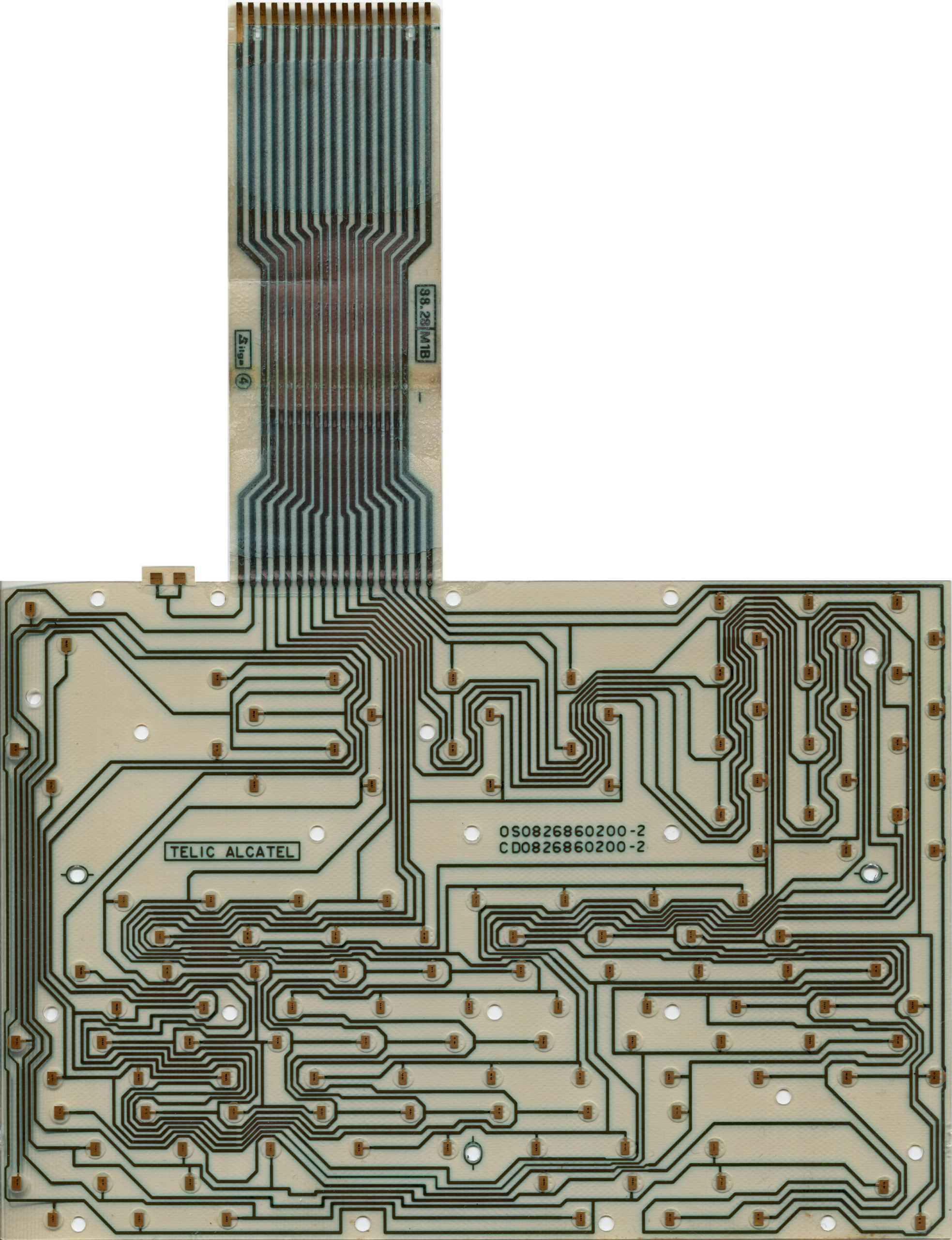
  • Minitel terminal disassembled, minitel pcb and keyboard removed. Check!
  • Keys rearranged on keyboard for better ZX81 support. Check!
Now comes the hard parts.
  • Designing circuit for retranslation of different keyboard matrix. In progress.
And things left to do.
  • Design pcb for composite input to CRT. Someone has done it before.
  • Built a RAM expansion circuit since 1k will not be sufficient, and an external connector will not be a great solution. I'm thinking about Wilf Rigter's 64k expansion.
  • Build a circuit to use power from the internal 8V or 12V.
  • Find a great way to mount it inside the terminal, and reattach keyboard.
Below are some atmosphere pictures.

You can see that I've rearranged the keys to match ZX81, compared to the original French layout.

Image

Image

Image

Re: VP100 replica project started (ZX81 in minitel terminal)

Posted: Fri Nov 27, 2020 12:07 am
by XavSnap

Re: VP100 replica project started (ZX81 in minitel terminal)

Posted: Fri Nov 27, 2020 6:49 am
by mrtinb
It’s difficult to see if this schematic of the 16k expansion, will also solve the keyboard translation. The chips on the schematic is just labeled Z1 - Z6, so it’s difficult to know what they do.

Even if this schematic will solve the keyboard translation, we don’t know that the different terminal models have the same keyboard matrix.

I’m thinking about fixing the keyboard matrix with latches and a ROM lookup table.

Re: VP100 replica project started (ZX81 in minitel terminal)

Posted: Fri Nov 27, 2020 11:15 am
by XavSnap
The keyboard is drive with latches and TTL ships.

The Minitel keyboard mapping...

… better to cut the PCB and rewiring the keyboard...to connect the zx keyboard socket… or rebuild a new PCB…
[Edit: Printed Mylar PCB… can't be changed :oops: ]

Image
picture from http://entropie.org/3615/index.php/2020 ... initel-1b/

Re: VP100 replica project started (ZX81 in minitel terminal)

Posted: Fri Nov 27, 2020 11:50 am
by mrtinb
Yes I had already found those pages. That's is my reference for my current prototype pcb.

Re: VP100 replica project started (ZX81 in minitel terminal)

Posted: Fri Nov 27, 2020 11:52 am
by 1024MAK
Maybe use a microcontroller to handle the keyboard translation?

The eight address lines from the ZX81 would be inputs. Five outputs from the microcontroller would go to the ULA keyboard inputs. Then you obviously need enough I/O pins to scan the keyboard...

If the microcontroller does not have enough outputs, there are various ways of expanding this number, including use of a 3 to 8 line decoder like a 74xx138 or similar.

Mark

Re: VP100 replica project started (ZX81 in minitel terminal)

Posted: Fri Nov 27, 2020 12:37 pm
by mrtinb
I'll try with the current approach. If I can't get it to work, I'll try with a microcontroller.

Re: VP100 replica project started (ZX81 in minitel terminal)

Posted: Fri Nov 27, 2020 4:38 pm
by msch
Martin, cool project!
Hopefully we will see this at the next ZX-Team meeting :D

Re: VP100 replica project started (ZX81 in minitel terminal)

Posted: Fri Nov 27, 2020 5:49 pm
by mrtinb
msch wrote: Fri Nov 27, 2020 4:38 pm Hopefully we will see this at the next ZX-Team meeting :D
Yes, I've got some problems to hack before it becomes a reality. But I'm working on it.

Re: VP100 replica project started (ZX81 in minitel terminal)

Posted: Wed Jan 06, 2021 10:53 pm
by mrtinb
I'm running a parallel approach here. I try to create the keyboard controller either in TTL logic or by a microcontroller.

From what I can read, the computer pulls address lines A8 - A15 LOW, one at a time when port $FE is read. The keyboard data is bit 0 - 4 in the response. The key pressed is pulled LOW for the key in one of the 8 groups corresponds to the address lines.

To make it easier on myself, I will connect the microcontroller to my existing keyboard controller, Wilf Rigter's ZXKBDv3. Then I don't have address decoding, but just the keyboard matrix. The rows are connected to the address line (row 0 - 7), and the columns are connected to the response on the data bus (column 0 - 4).

I have received an oscilloscope for Christmas. It's a Hantek 2C72 with 2 channels at 70 MHz. I think that should be fast enough for a microcomputer at 3.25 MHz.

Image

I'm trying to understand the signals to interpret and send from the microcontroller.

I assumed I would have 8 inputs which were mostly HIGH, and occasionally LOW, when the computer wanted to read one of the 8 groups of 5 keys. But when I measure with the oscilloscope I see a different picture. On the screenshot above, I have pressed the X key on the keyboard. The oscilloscope's channel 1 (yellow) is connected to row 0 (which behind the controller's circuitry is connected to A8). The oscilloscope's channel 1 (green) is connected to column 2 (which behind the controller's circuitry is connected to D2).

The picture is taken just as I press X. Before X is pressed row 0 is constantly at 0V, and column 2 is constantly at 5V. I had expected row 0 to be at 5V, and occasionally drop to 0V.

When X is pressed then row 0 go to 5V, and row 0 and column 2 are shorted and follow each other. But now the signal drop to 0V occasionally whenever the computer polls for the key.

I don't know how to code this in the microcontroller, as there is no signal, I can test before the key is pressed.

So I assume I can set all rows and columns to HIGH-Z, and when I want to send a key press, I set column 2 to HIGH, and read row 0, and detect when it is pulled LOW. Then I pull column 2 LOW until row 0 is HIGH again. Then I set all rows and columns back to HIGH-Z.

Please correct me if I have misunderstood.