
So, please remind me what test gear you have / can borrow.
The video comes from IC20 (74LS86), so if you have a logic probe, logic analyser or oscilloscope, test IC20 pins 4, 5 & 6.
Check IC9 (74LS165) pins 1, 2, 7 and 9. Also ensure that the link marked A--C is made (should be simply a PCB track).
Mark
My first ZX80.
-
1024MAK

- Posts: 5118
- Joined: Mon Sep 26, 2011 10:56 am
- Location: Looking forward to summer in Somerset, UK...
Re: My first ZX80.
ZX81 Variations
ZX81 Chip Pin-outs
ZX81 Video Transistor Buffer Amp
 Standby alert
There are four lights!
Step up to red alert. Sir, are you absolutely sure? It does mean changing the bulb
Looking forward to summer later in the year.
ZX81 Chip Pin-outs
ZX81 Video Transistor Buffer Amp
There are four lights!
Step up to red alert. Sir, are you absolutely sure? It does mean changing the bulb
Looking forward to summer later in the year.
-
Muttley Black

- Posts: 48
- Joined: Thu Apr 18, 2019 7:54 am
Re: My first ZX80.
Hello Mark.
Here is the results with logic probe (ttl):
IC20 (74LS86)
PIN 4: pulsing HI
PIN 5: pulsing LOW
PIN 6: pulsing HI
IC9 (74LS165)
PIN 1: pulsing HI
PIN 2: LOW
PIN 7: pulsing HI
pin 9: pulsing LOW
About the A--C is connected (pcb track)
I also have a simple cheep logic analyser if it is more helpful.
Thank you
-
1024MAK
- Posts: 5118
- Joined: Mon Sep 26, 2011 10:56 am
- Location: Looking forward to summer in Somerset, UK...
Re: My first ZX80.
It is worthwhile lifting and then reseating (pushing them back in) all socketed chips.
IC9 (74LS165) is the parallel to serial shift register that converts each byte of display pixel data to the bit stream used to form the video signal.
It may be worthwhile attaching your logic analyser to the data bus inputs:
Pin 11 D0
Pin 12 D1
Pin 13 D2
Pin 14 D3
Pin 3 . D4
Pin 4 . D5
Pin 5 . D6
Pin 6 . D7
Pin 2 is the pixel clock.
Pin 1 is the load latch/strobe.
Pin 9 is the normal (black on white) output.
Pin 7 is the “inverted” (white on black) output.
Most of the time the data should be lots os zero bytes, as most of the screen is blank. But hopefully you will see the pixel data of an inverse K in the bottom left hand corner.
Mark
Last edited by 1024MAK on Sun Jun 14, 2020 3:42 am, edited 1 time in total.
Reason: Whoops! I left out D2 data pin. Now edited and corrected.
Reason: Whoops! I left out D2 data pin. Now edited and corrected.
ZX81 Variations
ZX81 Chip Pin-outs
ZX81 Video Transistor Buffer Amp
Standby alert
There are four lights!
Step up to red alert. Sir, are you absolutely sure? It does mean changing the bulb
Looking forward to summer later in the year.
ZX81 Chip Pin-outs
ZX81 Video Transistor Buffer Amp
There are four lights!
Step up to red alert. Sir, are you absolutely sure? It does mean changing the bulb
Looking forward to summer later in the year.
-
Muttley Black
- Posts: 48
- Joined: Thu Apr 18, 2019 7:54 am
Re: My first ZX80.
Thank you Mark. I report back when i test the IC9 with my logic analyser.
By the way, the only ic’s that are socketed are ic 13 that some time they changed it and the Cpu.
Thank you.
By the way, the only ic’s that are socketed are ic 13 that some time they changed it and the Cpu.
Thank you.
Re: My first ZX80.
When I first exchanged the Z80 I got a blank screen without the [K].. similar to yours.. then I switched back the original Z80 and the [K].. why don't you just invokes your good luck and removes and resocket the Z80..
Be aware that the socket in my case at least has small holes and you have to be really careful when putting it back..
Be aware that the socket in my case at least has small holes and you have to be really careful when putting it back..
Ernesto
ZX80 USA, ZX81UK, ZX Spectrum, ZX Spectrum+, ZX Spectrum 128+ UK, ZX Spectrum +2/A, Sinclair QL, CZ1000, CZ1500, CZ2000, CZ1000Plus, CZ1500Plus, CZ Spectrum, CZ Spectrum Plus, TK83, TK85, TK90X, TK95. TS2068. And more to come
ZX80 USA, ZX81UK, ZX Spectrum, ZX Spectrum+, ZX Spectrum 128+ UK, ZX Spectrum +2/A, Sinclair QL, CZ1000, CZ1500, CZ2000, CZ1000Plus, CZ1500Plus, CZ Spectrum, CZ Spectrum Plus, TK83, TK85, TK90X, TK95. TS2068. And more to come
-
Muttley Black
- Posts: 48
- Joined: Thu Apr 18, 2019 7:54 am
Re: My first ZX80.
I have tried this. With 3 Z80 CPU’s.
-
Muttley Black
- Posts: 48
- Joined: Thu Apr 18, 2019 7:54 am
Re: My first ZX80.
Good morning Mark.
Here is two screen captures for the logic analyser, starting from DO to D7:
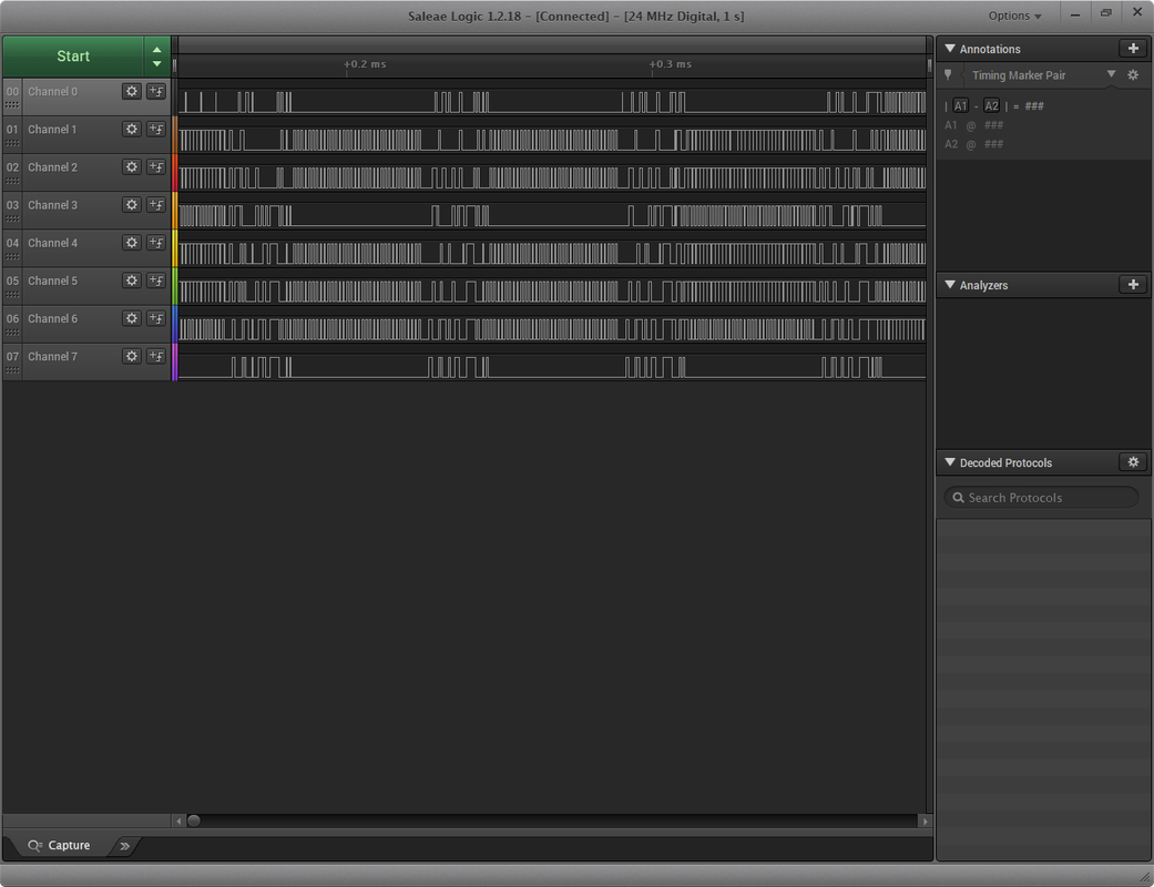

Looks like we have a traffic there.
Here is two screen captures for the logic analyser, starting from DO to D7:
Looks like we have a traffic there.
Re: My first ZX80.
Just my two pence worth.
I had a similar problem with my 80, blank screen etc and Marks advice was that the z80 socket could be at fault which I foolishly dismissed as continuity was to be found on all the pins etc and changing CPU's did nothing.
In desperation I removed the socket and on very close inspection found the pins to be ever so slightly corroded internally and whilst a reading would show on the multi meter pressed hard into the socket pins there was not enough contact being made to the CPU.
One replaced socket later and double checked that that where it needed soldering on both sides of the board it was soldered, I ended up with a perfectly working ZX80.
My point being is that the CPU socket on the ZX80 is usually the small hole type which makes it difficult to see if the pins are dirty inside, and just because it show continuity with a meter doesn't mean the CPU is receiving everything it should.
Also the circuit board pads on the ZX80 are nice and big compared to say the ZX81 or spectrum and not as easy to damage,I found removing and replacing the socket a very easy thing to do.
-
Muttley Black
- Posts: 48
- Joined: Thu Apr 18, 2019 7:54 am
Re: My first ZX80.
Hello Moggy.
i have test the cpu socket (pin1 to pin2, pin2 to pin3 etc) for sorts and it is ok. Also with the cpu plugged, i test the continuity from solder side to cpu leg (in every pin/leg) through the socket and all are ok.
One think i want to mention, is that when i got the 80, there was two cables (same type) soldered to board. The first on voltage regulator( 5v leg / ground) and the second next to modulator (left side of R31 / ground). I don't know the reason why previous owner did that. Also looks like they have replaced the resistor R32.
Here are the photos:


Other components that have replaced from previous owner are, C15 & IC13.


i have test the cpu socket (pin1 to pin2, pin2 to pin3 etc) for sorts and it is ok. Also with the cpu plugged, i test the continuity from solder side to cpu leg (in every pin/leg) through the socket and all are ok.
One think i want to mention, is that when i got the 80, there was two cables (same type) soldered to board. The first on voltage regulator( 5v leg / ground) and the second next to modulator (left side of R31 / ground). I don't know the reason why previous owner did that. Also looks like they have replaced the resistor R32.
Here are the photos:
Other components that have replaced from previous owner are, C15 & IC13.
Re: My first ZX80.
It goes against logic I know but the readings on my socket and CPU were ok too but as soon as I changed the socket everything worked why I do not know except the pins inside the socket when closely examined were corroded.
As for the wires on the regulator why some one would use co-axial signal wire on a power chip I don't have an answer but looking at the picture of the regulator everything around it looks messy and is the ground pin even connected?
As for the wires on the regulator why some one would use co-axial signal wire on a power chip I don't have an answer but looking at the picture of the regulator everything around it looks messy and is the ground pin even connected?