
Thank you Mark.1024MAK wrote: ↑Thu Jun 18, 2020 12:21 am The following is in reference you your last screen.
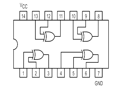
There must be pulses on the pixel clock input, because there are outputs on both the normal and the inverted outputs shortly after the latch/strobe input sees a pulse.
We don’t know what data bits D4 to D7 are, but based on the output, I suspect at least D5 and D6 were high, and the output stays high reflecting D3 being high. Then the output goes low reflecting D2, D1 and D0 being low.
Based on this, I would say IC9 is working okay
Mark
My first ZX80.
-
Muttley Black

- Posts: 48
- Joined: Thu Apr 18, 2019 7:54 am
Re: My first ZX80.
-
Muttley Black
- Posts: 48
- Joined: Thu Apr 18, 2019 7:54 am
Re: My first ZX80.
I order a 16ch logic analyser to be able to help me in this case but also in the future.
Starting read stuff on the internet about how the zx80 work.
According the following photos, that are part of "clock generator", i made same measurements.
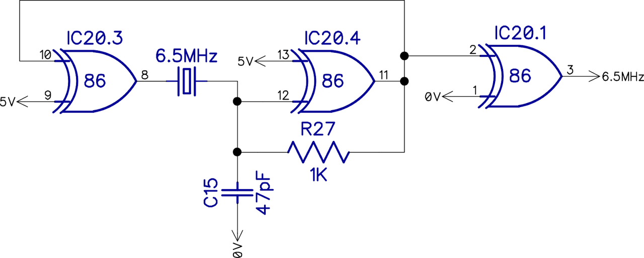
I plug my logic analyser and did some measurements and the results are the following:
X1: in both sides i got 6MHZ with some pulses at 8MHZ
IC20 PIN3: 6MHZ
IC20 PIN8: 6MHZ
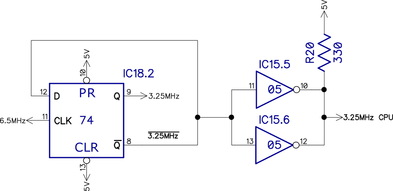
IC18 PIN8: 3MHZ with some pulses at 3.429MHZ
IC18 PIN9: 3MHZ with some pulses at 3.429MHZ
IC15 PIN10: 3MHZ with some pulses at 3.429MHZ
IC15 PIN12: 3MHZ with some pulses at 3.429MHZ
I don't know if i at moving the right way but we will see.
Starting read stuff on the internet about how the zx80 work.
According the following photos, that are part of "clock generator", i made same measurements.
I plug my logic analyser and did some measurements and the results are the following:
X1: in both sides i got 6MHZ with some pulses at 8MHZ
IC20 PIN3: 6MHZ
IC20 PIN8: 6MHZ
IC18 PIN8: 3MHZ with some pulses at 3.429MHZ
IC18 PIN9: 3MHZ with some pulses at 3.429MHZ
IC15 PIN10: 3MHZ with some pulses at 3.429MHZ
IC15 PIN12: 3MHZ with some pulses at 3.429MHZ
I don't know if i at moving the right way but we will see.
-
1024MAK

- Posts: 5118
- Joined: Mon Sep 26, 2011 10:56 am
- Location: Looking forward to summer in Somerset, UK...
Re: My first ZX80.
Testing on resonator or crystal connections, or on the chips or other components they connect to can alter the oscillator frequency, or stop the oscillator from working. So I normally recommend testing on the output of the logic gate that feeds the rest of the system (IC20 pin 11 or IC20 pin 3 in this case).
Back in the 1980s, the design of crystal (and resonator) oscillators was considered a black art even within electronic engineering!
The frequencies of about 6MHz and about 3MHz are about right. The frequency of the resonator is not as accurate as a crystal, so some machines (ZX80 and ZX81) don’t run at exactly 6.5MHz and 3.25MHz but may run a little slower (lower frequency) or a little faster (higher frequency).
Mark
ZX81 Variations
ZX81 Chip Pin-outs
ZX81 Video Transistor Buffer Amp
 Standby alert
There are four lights!
Step up to red alert. Sir, are you absolutely sure? It does mean changing the bulb
Looking forward to summer later in the year.
ZX81 Chip Pin-outs
ZX81 Video Transistor Buffer Amp
There are four lights!
Step up to red alert. Sir, are you absolutely sure? It does mean changing the bulb
Looking forward to summer later in the year.
-
Muttley Black
- Posts: 48
- Joined: Thu Apr 18, 2019 7:54 am
Re: My first ZX80.
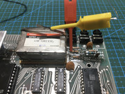
Ok Mark. I am going to plug the logic analyser on IC20 and I report back with photos.
Thank you
Thank you
-
Muttley Black
- Posts: 48
- Joined: Thu Apr 18, 2019 7:54 am
Re: My first ZX80.
Here is the results from IC20, PINS: 1,2,3,11,12,13.
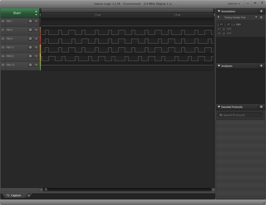
And here again from IC20 but this time from PINS: 4,5,6,8,9,10.
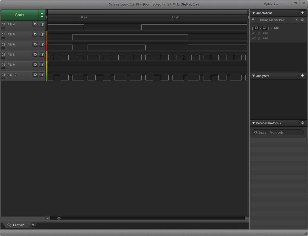
And here again from IC20 but this time from PINS: 4,5,6,8,9,10.
-
Muttley Black
- Posts: 48
- Joined: Thu Apr 18, 2019 7:54 am
Re: My first ZX80.
Hello Mark.
I hope you doing ok. I am back with a Hantek DSO5102P Oscilloscope. I am new with that kind of tool but if that could help to fix this beauty i am all ears to mesure anything you want me to.
I hope you doing ok. I am back with a Hantek DSO5102P Oscilloscope. I am new with that kind of tool but if that could help to fix this beauty i am all ears to mesure anything you want me to.
-
1024MAK
- Posts: 5118
- Joined: Mon Sep 26, 2011 10:56 am
- Location: Looking forward to summer in Somerset, UK...
Re: My first ZX80.
I’ll have a look/think...
Mark
Mark
ZX81 Variations
ZX81 Chip Pin-outs
ZX81 Video Transistor Buffer Amp
Standby alert
There are four lights!
Step up to red alert. Sir, are you absolutely sure? It does mean changing the bulb
Looking forward to summer later in the year.
ZX81 Chip Pin-outs
ZX81 Video Transistor Buffer Amp
There are four lights!
Step up to red alert. Sir, are you absolutely sure? It does mean changing the bulb
Looking forward to summer later in the year.
-
Muttley Black
- Posts: 48
- Joined: Thu Apr 18, 2019 7:54 am
Re: My first ZX80.

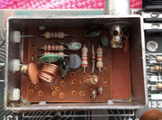
Following pictures taken with composite technique. That’s mean that the problem is on modulator I guess...
I want to keep it in original shape, so I desolder the modulator and have a look inside if anything is broken.
-
1024MAK
- Posts: 5118
- Joined: Mon Sep 26, 2011 10:56 am
- Location: Looking forward to summer in Somerset, UK...
Re: My first ZX80.
Ahh, no wonder why trying to work out what was going on with your board made my brain hurt...
The same modulator is used in various 1980s ‘British’ home computers, so it may be a good idea to ask if anyone has a used (or new old stock) one that they can send to you.
If you do want to try repair, keep in mind that they are RF oscillators and are a bit of a black art. Don’t disturb any of the coils/inductors. Replace transistors like for like. It’s unlikely any ceramic capacitors would have failed. Measure the resistors (some may have their resistance affected by other in circuit components).
Mark
ZX81 Variations
ZX81 Chip Pin-outs
ZX81 Video Transistor Buffer Amp
Standby alert
There are four lights!
Step up to red alert. Sir, are you absolutely sure? It does mean changing the bulb
Looking forward to summer later in the year.
ZX81 Chip Pin-outs
ZX81 Video Transistor Buffer Amp
There are four lights!
Step up to red alert. Sir, are you absolutely sure? It does mean changing the bulb
Looking forward to summer later in the year.
-
Muttley Black
- Posts: 48
- Joined: Thu Apr 18, 2019 7:54 am
Re: My first ZX80.
In case that I can’t find a solution, what is the best way for a composite mod? I want to hide it inside the modulator case. Any link please?
Thank you
Thank you