
I don’t think your TV likes the total loss of signal when the ZX80 is not displaying a signal.
Does it do the same thing if you run a program that does not wait for input, like this:
10 FOR A=0 TO 5000
20 NEXT A
And hence while doing this, it doesn’t produce a TV signal.
Mark
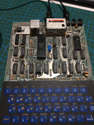
My first ZX80.
-
1024MAK

- Posts: 5118
- Joined: Mon Sep 26, 2011 10:56 am
- Location: Looking forward to summer in Somerset, UK...
Re: My first ZX80.
ZX81 Variations
ZX81 Chip Pin-outs
ZX81 Video Transistor Buffer Amp
 Standby alert
There are four lights!
Step up to red alert. Sir, are you absolutely sure? It does mean changing the bulb
Looking forward to summer later in the year.
ZX81 Chip Pin-outs
ZX81 Video Transistor Buffer Amp
There are four lights!
Step up to red alert. Sir, are you absolutely sure? It does mean changing the bulb
Looking forward to summer later in the year.
-
Muttley Black

- Posts: 48
- Joined: Thu Apr 18, 2019 7:54 am
Re: My first ZX80.
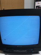
After hit "RUN" tv loss signal and get back with "0/20" and big vertical black line, as before.
-
Muttley Black
- Posts: 48
- Joined: Thu Apr 18, 2019 7:54 am
Re: My first ZX80.
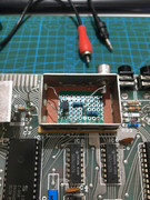
Yesterday I tried to put a modulator from a zx spectrum.
This make my zx80 post a great picture.
The problem was that the rca was at the other way. I have the USA zx80.
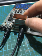
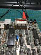
So I decided to put the pcb of zx spectrum modulator to the zx80 case. But needed also to put the pcb the other way around cause only that way fit.
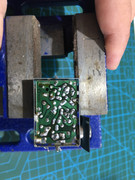


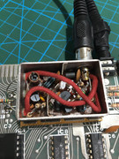
That’s don’t work. Cause of the wight of the cable and that are goes up from all components, the picture is bad. If i take out the red cables from the case the picture is much better.
So, don’t try this mod if you have the USA zx80.
This make my zx80 post a great picture.
The problem was that the rca was at the other way. I have the USA zx80.
So I decided to put the pcb of zx spectrum modulator to the zx80 case. But needed also to put the pcb the other way around cause only that way fit.
That’s don’t work. Cause of the wight of the cable and that are goes up from all components, the picture is bad. If i take out the red cables from the case the picture is much better.
So, don’t try this mod if you have the USA zx80.
-
Muttley Black
- Posts: 48
- Joined: Thu Apr 18, 2019 7:54 am
Re: My first ZX80.
Some news.
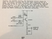
I made that circuit again:

But with the difference that i didn’t use the 100ohm resistor at all. Also i replace R32 resistor on the motherboard with diode 1N4148 with cathode looking at sync ic19 way.
The results:
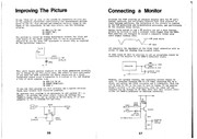
All this came with something I read from an old book about improving ZX80 picture. Anyway, the following circuit didn’t work from me also, but I keep the 1N4149 for do some test one more time. That’s how i got that results.
Transistors that I tried are BC547 & 2N2222. Both work.
Here is what I talk about:

And all the page:
Any explanation from the masters?
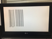
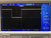
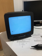
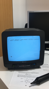
And here is the video output. Crystal clear picture on TV but no back porch signal.
I made that circuit again:
But with the difference that i didn’t use the 100ohm resistor at all. Also i replace R32 resistor on the motherboard with diode 1N4148 with cathode looking at sync ic19 way.
The results:
All this came with something I read from an old book about improving ZX80 picture. Anyway, the following circuit didn’t work from me also, but I keep the 1N4149 for do some test one more time. That’s how i got that results.
Transistors that I tried are BC547 & 2N2222. Both work.
Here is what I talk about:
And all the page:
Any explanation from the masters?
And here is the video output. Crystal clear picture on TV but no back porch signal.
-
1024MAK
- Posts: 5118
- Joined: Mon Sep 26, 2011 10:56 am
- Location: Looking forward to summer in Somerset, UK...
Re: My first ZX80.
With analogue video signals, because the video signal is rather complex, both in timing and in respect of the different voltage levels, if the signal seen by the monitor is out of specification, the TV or monitor will not display a stable video picture.
Because Sinclair used a simple mixer circuit (using just resistors) to combine the video and synchronisation signals, which was optimised only for use with the type of modulator that they fitted, most TV or monitors will not be happy if you directly wire the (former) modulator input signal to the composite video input of the TV or monitor. Keep in mind that the input impedance (AC equivalent to resistance for DC) for a composite video input on a TV or monitor is specified as 75 ohms.
In the simple single transistor buffer circuit designed for the ZX81, all this is doing is providing a higher current (lower impedance) output (because it's not wise to try to directly connect the ULA video output pin to the relatively low 75 ohms impedance input of a TV or monitors composite video input. The 13mA to 40mA that will try to flow is not healthy for the ULA (13mA at 1V, but the ULA tries to output a higher voltage as it's supposed to be a logic chip). The simple single transistor buffer circuit does not significantly change the levels (which are still too high). But instead it's the transistor that delivers the output current to the TV or monitors composite video input, and the load on the ULA is much reduced.
With the ZX80, the available current from it's video output is far too low for most TV or monitors. So a buffer transistor is required. But because the signal levels are different, a different arrangement of components is needed around it. The 1N4148 diode is used, because the active sync signal (that is, it's considered active when it is low) has to take the output video signal to as near to 0V as possible. Black video level should be about 0.3V and peak (maximum white video) should be no more than 1V. The values of the various resistors are intended to get the video signal close to these voltages.
See this diagram of the levels that a video signal should be:

Note that some TV or monitors will still work if the input voltages are a bit high, as they either use a coupling capacitor, or use clamping circuits to restore the signal to within the correct maximum level.
I hope that helps
Mark
Because Sinclair used a simple mixer circuit (using just resistors) to combine the video and synchronisation signals, which was optimised only for use with the type of modulator that they fitted, most TV or monitors will not be happy if you directly wire the (former) modulator input signal to the composite video input of the TV or monitor. Keep in mind that the input impedance (AC equivalent to resistance for DC) for a composite video input on a TV or monitor is specified as 75 ohms.
In the simple single transistor buffer circuit designed for the ZX81, all this is doing is providing a higher current (lower impedance) output (because it's not wise to try to directly connect the ULA video output pin to the relatively low 75 ohms impedance input of a TV or monitors composite video input. The 13mA to 40mA that will try to flow is not healthy for the ULA (13mA at 1V, but the ULA tries to output a higher voltage as it's supposed to be a logic chip). The simple single transistor buffer circuit does not significantly change the levels (which are still too high). But instead it's the transistor that delivers the output current to the TV or monitors composite video input, and the load on the ULA is much reduced.
With the ZX80, the available current from it's video output is far too low for most TV or monitors. So a buffer transistor is required. But because the signal levels are different, a different arrangement of components is needed around it. The 1N4148 diode is used, because the active sync signal (that is, it's considered active when it is low) has to take the output video signal to as near to 0V as possible. Black video level should be about 0.3V and peak (maximum white video) should be no more than 1V. The values of the various resistors are intended to get the video signal close to these voltages.
See this diagram of the levels that a video signal should be:
Note that some TV or monitors will still work if the input voltages are a bit high, as they either use a coupling capacitor, or use clamping circuits to restore the signal to within the correct maximum level.
I hope that helps
Mark
ZX81 Variations
ZX81 Chip Pin-outs
ZX81 Video Transistor Buffer Amp
Standby alert
There are four lights!
Step up to red alert. Sir, are you absolutely sure? It does mean changing the bulb
Looking forward to summer later in the year.
ZX81 Chip Pin-outs
ZX81 Video Transistor Buffer Amp
There are four lights!
Step up to red alert. Sir, are you absolutely sure? It does mean changing the bulb
Looking forward to summer later in the year.
-
Muttley Black
- Posts: 48
- Joined: Thu Apr 18, 2019 7:54 am
Re: My first ZX80.
Thank you so much Mark. I will study all the above.
By the way I was ready to post some changes. I decided to make the composite video to work on my mini crt and only. The following changes I made don’t work with lcd tv:
I did make again the following circuit but, i didn’t change R30 with 470ohm resistor. I keep the 1k. I put 680ohm resistor at R33. And finally I put 2x 100ohm resistor and not 120ohm as the circuit says.
And the results:
-
Muttley Black
- Posts: 48
- Joined: Thu Apr 18, 2019 7:54 am

Re: My first ZX80.
My actual mod doesn't have the 18/33 ohm resistance.. and the diode I guess is to lower the amplitude of signal.. am I wrigt?
I didn't had any luck with the 555 mod..
I'm trying (probably this week) another mod I found for TK83 Brazilian clones that don't use a ULA and doesn't generates a back porch either..
I couldn't get a bright image in one of these TK83 on the same TV (but ZX80 goes bright once you get sync) .. perhaps I'll make a new post about that...
Ernesto
ZX80 USA, ZX81UK, ZX Spectrum, ZX Spectrum+, ZX Spectrum 128+ UK, ZX Spectrum +2/A, Sinclair QL, CZ1000, CZ1500, CZ2000, CZ1000Plus, CZ1500Plus, CZ Spectrum, CZ Spectrum Plus, TK83, TK85, TK90X, TK95. TS2068. And more to come
ZX80 USA, ZX81UK, ZX Spectrum, ZX Spectrum+, ZX Spectrum 128+ UK, ZX Spectrum +2/A, Sinclair QL, CZ1000, CZ1500, CZ2000, CZ1000Plus, CZ1500Plus, CZ Spectrum, CZ Spectrum Plus, TK83, TK85, TK90X, TK95. TS2068. And more to come
-
1024MAK
- Posts: 5118
- Joined: Mon Sep 26, 2011 10:56 am
- Location: Looking forward to summer in Somerset, UK...
Re: My first ZX80.
The more conventional place to put one or more diodes to reduce the output voltage level is in the transistor base (input) circuit. Because the transistor is in the emitter follower configuration, the output voltage follows the input voltage minus the base-emitter voltage (approximately 0.6V).
Mark
Mark
ZX81 Variations
ZX81 Chip Pin-outs
ZX81 Video Transistor Buffer Amp
Standby alert
There are four lights!
Step up to red alert. Sir, are you absolutely sure? It does mean changing the bulb
Looking forward to summer later in the year.
ZX81 Chip Pin-outs
ZX81 Video Transistor Buffer Amp
There are four lights!
Step up to red alert. Sir, are you absolutely sure? It does mean changing the bulb
Looking forward to summer later in the year.