Page 1 of 6
Creating Wilf Rigter's ZXKBD v3
Posted: Mon Dec 21, 2015 9:51 pm
by mrtinb
Hi

I found Wilf Rigter's project to build an external connected keyboard like the version from Memotech.
I've found this schematic

on this page:
http://www.user.dccnet.com/wrigter/inde ... XKBDv3.htm
Unfortunately there is a component in the schematics, that I don't know: "RN1 5.1K". Does anyone have an idea what this part is?
This is my first PCB-project, and I'm trying to create the PCB.
/Martin
Re: Creating Wilf Rigter's ZXKBD v3
Posted: Mon Dec 21, 2015 9:53 pm
by XorA
mrtinb wrote:Hi
Unfortunately there is a component in the schematics, that I don't know: "RN1 5.1K". Does anyone have an idea what this part is?
Almost certainly Resistor Network!
Re: Creating Wilf Rigter's ZXKBD v3
Posted: Mon Dec 21, 2015 10:02 pm
by mrtinb
XorA wrote:Almost certainly Resistor Network!
Is that a component, or just a schematic way to show multiple resistors connected?
/Martin
Re: Creating Wilf Rigter's ZXKBD v3
Posted: Mon Dec 21, 2015 10:09 pm
by mrtinb
XorA wrote:Almost certainly Resistor Network!
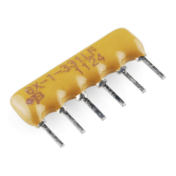
Ah! I found this component
/Martin
Re: Creating Wilf Rigter's ZXKBD v3
Posted: Mon Dec 21, 2015 10:32 pm
by PokeMon
You can use single resistors as well.
The network just save space while one end of resistors are connected all together to allow easy multiple pull down oder pull up resistors in one package.
Re: Creating Wilf Rigter's ZXKBD v3
Posted: Tue Dec 22, 2015 2:59 am
by 1024MAK
Hello Martin, welcome to our forum

mrtinb wrote:Unfortunately there is a component in the schematics, that I don't know: "RN1 5.1K". Does anyone have an idea what this part is?
It is a resistor network. This type has six 5.1k ohm resistors, all of which connect one end of each resistor to a common terminal (so this type would have 7 pins). As Pokemon says, they are commonly used for pull-up (to the +V rail) or pull-down (to 0V / GND). Be careful when ordering, as some have individual resistors with no common terminal. Also double check (including testing using a meter on the resistance range) which terminal is common. As putting these in the wrong way round can cause many weird fault symptoms...
If you can't get a 6 way type, a 7, 8 or 9 way type is fine (just ignore the pins you don't need. Or use normal resistors.
If you can't get 5.1k ohm, 4.7k ohm
may work.
Good luck
Mark
PS there is a requirement to post up lots of details of your progress, including tech p0rn photos

Re: Creating Wilf Rigter's ZXKBD v3
Posted: Tue Dec 22, 2015 11:02 am
by mrtinb
On the keyboard it would be nice to have keys for cursor that enables both [Shift] combined with [5], [6], [7] and [8].
As the keys have 4 pins one set can be connected to [Shift] and the other to e.g. [5].

Do I need a component that delays e.g. [5] so [Shift] reaches the computer first?
/Martin
Re: Creating Wilf Rigter's ZXKBD v3
Posted: Tue Dec 22, 2015 11:23 am
by 1024MAK
Just because switches have four pins does not mean that there are two sets of contacts inside

Most click type PCB mounting switches have four pins for stability.
So check carefully what the supplier says.
Or get a sample (one only) and use a multimeter to test...
See the
wikipedia entry to understand all the meanings that tell you how many contacts there are and what type of operation they have.
Mark
Re: Creating Wilf Rigter's ZXKBD v3
Posted: Thu Jan 07, 2016 11:30 pm
by mrtinb
Now the PCB design is complete. The board (10 cm x 5 cm) has been ordered in China. It looks quite confusing but this is my first board, and all connections have been made with autoroute.
Now I need to order the ics, sockets, connectors, resistors, diodes and capacitor. Keyboard will be connected with ribbon cable. The 9-pin joystick port will also connected with ribbon cable.
/Martin
Re: Creating Wilf Rigter's ZXKBD v3
Posted: Fri Jan 08, 2016 6:24 am
by Paul
I would like to say that all power lines should be much thicker.
kind regards Paul