RF Video Distortion

Discussions about Sinclair ZX80 and ZX81 Hardware
User avatar
RetroMike
Posts: 47
Joined: Mon Jun 09, 2014 1:33 am

RF Video Distortion

Post by RetroMike »

My replacement Zed arrived late last week, and straight out of the box I can see there's a bit of a problem with the TV picture, as you can see in the pic below:

Image

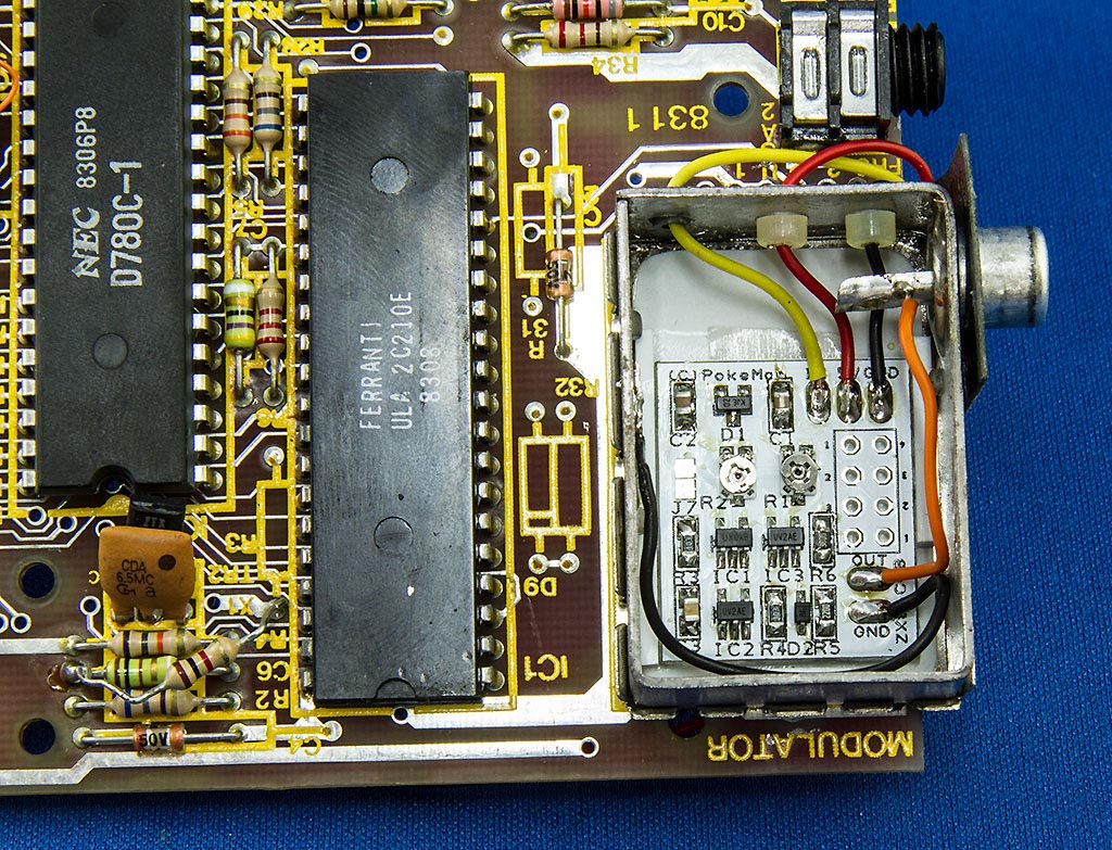
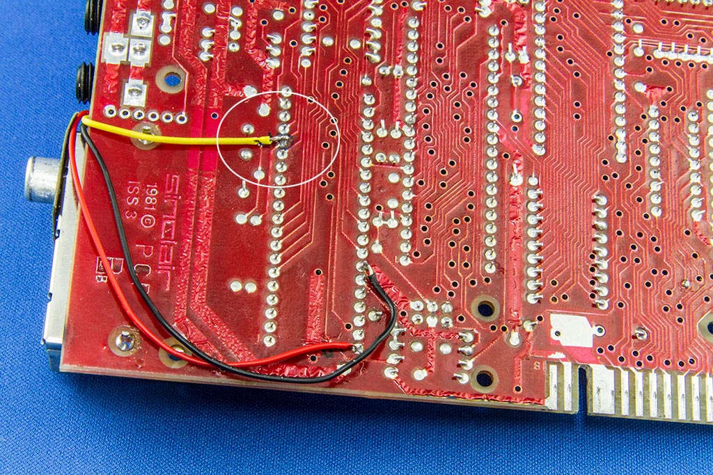
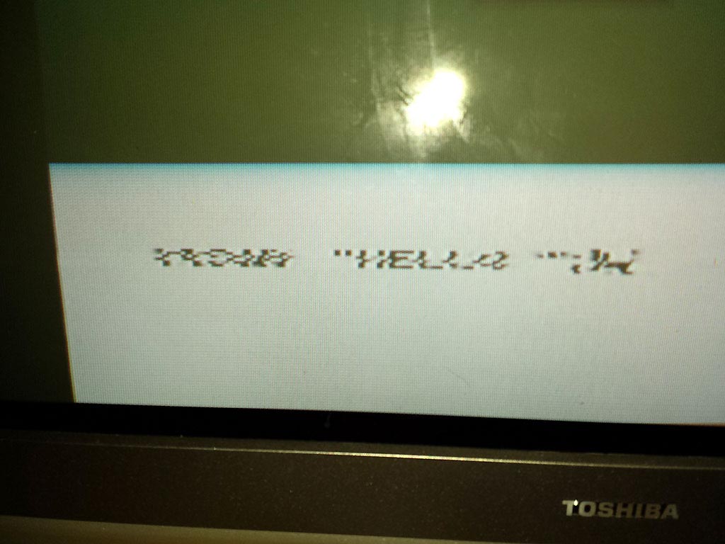
The further right on the screen you get, the worse the picture is and it's garbage by the time you're half-way across. The program listing area at the top is pretty crap too, and no amount of tuning of the TV will make it any better. Now I have one of Pokemon's ZX8-CCBs in the workshop, and was wondering if the issue will be fixed simply by installing that, or whether it's somewhere else that the problem lies, rather than in that innocent looking little silver box. :?:

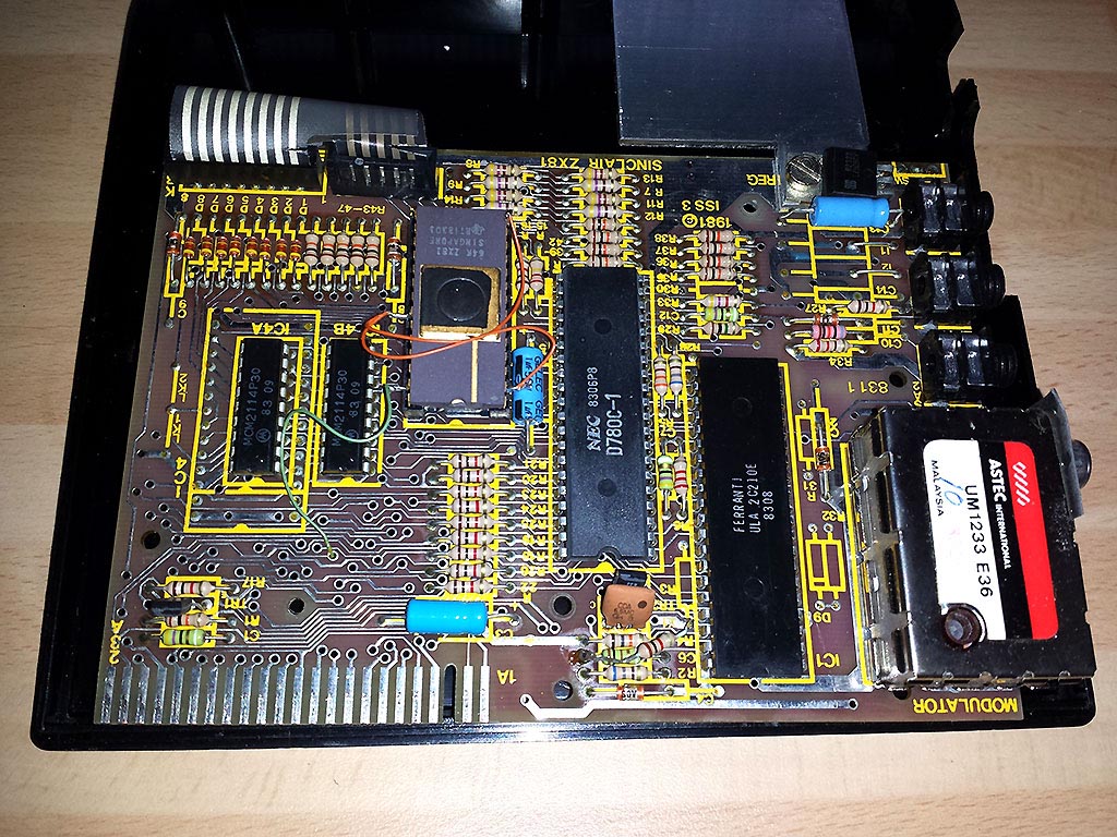
Here's a general shot of the topside of the board - a phone pic, so you'll have to excuse the poor shot:

Image

D'ya think I might need a new keyboard membrane? ;)

Any clues, encouragement, suggestions or humorous comments are gratefully received :)

Mike.
Moggy
Posts: 3266
Joined: Wed Jun 18, 2008 2:00 pm

Re: RF Video Distortion

Post by Moggy »

Try it with a rampack attached to rule out a duff cell in the on-board ram other than that a failing ULA perhaps, does it do it from the off or when the ULA gets warm?

As for the membrane forget it the new ones are so stiff it's like pressing granite! Get the board out of the cases mount it on a base board (runs a lot cooler) find one of the many external keyboards on flea bay , Memotech Fuller Kaydee Crofton etc attach ZXpand +AY unit then don't look back. :D :lol:

As for any complaints about ruining an original collectors piece by doing so, my philosophy is they are not for putting in glass cages ,just use the bloody thing there's 1000's left out there and they are not Rembrants and will never fetch Ferrari money so not exactly a pension plan are they? :D


Sorry for crap quality pic.
Attachments
board1.GIF
board1.GIF (117.37 KiB) Viewed 5249 times
User avatar
PokeMon
Posts: 2264
Joined: Sat Sep 17, 2011 6:48 pm

Re: RF Video Distortion

Post by PokeMon »

Is it via modulator ?
You may try the ZX8-CCB for it, modern LCD TVs are not very happy with old signals from the 80ies, with some timing error, too.
Also you could try an old CRT TV would maybe give a much better picture.
But with ZX8-CCB should work even better on video in.

I don't think that there is a ram issue. The video distortion does not belong to a ram error.
User avatar
RetroMike
Posts: 47
Joined: Mon Jun 09, 2014 1:33 am

Re: RF Video Distortion

Post by RetroMike »

Thanks for the input guys... it won't hurt to try a RAM pack on - I have three plus a ZXp already! :lol:

The machine is running via the modulator on a CRT TV at the moment... a great big one that takes up most of the desk! :geek: It doesn't do anything on the flat panel I have nearby, but that's a monitor rather than a flat panel TV.

If I could solder the ZX8-CCB in carefully I could see whether it's gonna work before I spend too much time on it. If the ULA is on the blink, what's the damage on a new one, roughly?
Moggy
Posts: 3266
Joined: Wed Jun 18, 2008 2:00 pm

Re: RF Video Distortion

Post by Moggy »

User avatar
RetroMike
Posts: 47
Joined: Mon Jun 09, 2014 1:33 am

Re: RF Video Distortion

Post by RetroMike »

Thanks Moggy, I'll put a watch on that in case the CCB doesn't cure the issue :)
User avatar
PokeMon
Posts: 2264
Joined: Sat Sep 17, 2011 6:48 pm

Re: RF Video Distortion

Post by PokeMon »

I don't think it is an ULA issue. Normally the ULA doesn't output pixel data at all if something internal wrong/too hot.
This could also be the SYNC via WAIT mechanism with possible dead transistor TR1 (see schematic).
zx81wait.jpg
zx81wait.jpg (54.57 KiB) Viewed 5166 times
You should try to enter some program lines like

10 PRINT
20 PRINT
30 PRINT

to see if this effect is getting more or less over several screen rows.

And it is worth to test this in FAST mode as well, as the ZX81 WAIT Sync does apply in SLOW mode only.
In FAST mode picture is generated 100% in software which omits the TR1 circuit.
FAST can be achieved via SHIFT+NEWLINE (function mode) and then press F and NEWLINE again.

Hope you will make it. 8-)
User avatar
RetroMike
Posts: 47
Joined: Mon Jun 09, 2014 1:33 am

Re: RF Video Distortion

Post by RetroMike »

That's brilliant information, thanks. I've got the board on the desk in front of me now, about to install your CCB module, and a visual inspection of TR1 shows nothing, but I suspect that's often the case. I'll put the CCB in and check further once it's done. If it resolves the problem, then I shall do a little victory dance, but if not, I'll start giving TR1 some dirty looks and perhaps source a replacement. Any tips on that task would be appreciated as usual :)

I have to say - in the short time I've been on this board, I've been overwhelmed by the friendly, helpful nature of the posts. Your tolerance for inane newbie questions must be legendary. Thanks! :D
User avatar
RetroMike
Posts: 47
Joined: Mon Jun 09, 2014 1:33 am

Re: RF Video Distortion

Post by RetroMike »

Bah humbug! :(

I've connected up the CCB to the Zed, using a nice tidy install inside the modulator box, but now all I get is a blank screen on a composite input off my TV. Plugging and unplugging the power causes a brief flicker as whatever signal is lost, but that's it. My install mirrored the one in my other thread, but I wrapped the "input" wires over the side of the board and soldered them to the ULA legs from there. The black ground wire from the output side is attached to the side wall of the modulator box, and underneath is a sheet of plastic with upstands to hold the board steady, and a piece of double-sided tape to keep it in place.

Image

This is the underside. You can see i've marked an area where my tweezers resulted in the hot shroud being pierced exposing a little copper, but I've checked and there's no electrical contact being made. I'll secure it with hot-glue or insulation tape, or if I'm feeling sensible, replace the wire with some of the spare I cut off.

Image

I've tried nothing, and I'm all out of ideas :(
XorA
Posts: 98
Joined: Thu May 10, 2012 9:14 am
Location: Glasgow, Scotland, UK
Contact:

Re: RF Video Distortion

Post by XorA »

Did you remember with newer ULA you need to twiddle the pots as detailed in the fitting doc?
Post Reply