Page 2 of 2
Re: Simple Video Mod for 210ULA
Posted: Sat Apr 27, 2013 5:01 am
by zx81user
OK, I didn't expect to spend this much time on it but there are enough arguments to do a further investigation

.
First of all, the drawn current from ULA pin 16. I measured this compared to another TS1000 that still has the pin 16 connected to the RF modulator. In fact, the RF modulator draws a HIGHER current from pin 16 than my 3 diode solution. So although your circuit would be better, my circuit does not load the ULA more than the original RF modulator.
Second thing is that my simple trick works very well for a cheap chinese portable DVD player but didn't work for a Sony Bravia TV. For this reason I had to modify the circuit a bit, leaving 1 diode out and replacing it with a transistor. This also buffers the signal, so there is no longer a question about ULA pin load.
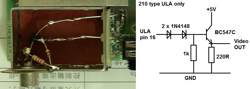
- Modified diode circuit with 2 diodes and transistor
- VideoBuffer210ULA.jpg (109.82 KiB) Viewed 8034 times
Third thing is the interference, or noise. This is still present in the signal but not amplified so it is no more or less than it was before. You could clip the voltage on the base of the transistor to get rid of that, but for me it doesn't really matter so I haven't tried that.
I got some picture here with the final result on my TV.
- IMG_1041.JPG
- The final result
- (1.14 MiB) Downloaded 921 times
Re: Simple Video Mod for 210ULA
Posted: Sat Apr 27, 2013 5:11 pm
by PokeMon
Thanks for the pictures. It looks good so far.
As the transistor solution this is what most people do for a simple discoupling of the video signal (in fact without the two diodes).
It could be a good idea to put a second smaller resistor (47R for example) between +5V and collector to protect the transistor against a possible shortcut at the output. But this is only a fineness as the transistor can simply be replaced and is very cheap. In comparison to a possibly shortened ULA output.
In your picture you can slightly see the noise of ULA output with the small stripes going from top to bottom.
This is what I meant before. But it's not very strong. This is dependend on the ULA version as well I think.
Anyway good job.

Re: Simple Video Mod for 210ULA
Posted: Sat Apr 27, 2013 10:06 pm
by gozzo
Correction to an earlier post where I said that the modulators RF out is coupled through a small value capacitor and was possible to feed composite out without removing/disconnecting the modulators innards ... not quite so - I was going on information from another source - not tried by myself until now - and it is incorrect that it is coupled by a capacitor, it is in fact coupled by a 47 ohm resistor and so this would load the ULA output excessively, although if adding a reasonable powerful buffer would probably be ok. Would need to disconnect the 47 ohm resistor from the phono socket for best results, and if you did want 'simultaneous' RF/composite out, add a small capacitor about 3300pf between the 47 ohm resistor and phono centre contact. I have seen on a speccy an electrolytic capacitor connected between the modulators input and the output socket, supposedly feeding composite out with the RF and working well, but as said above have found that the resistor kills the signal too much - removed it and works ok, and adding a 2700 pf does seem to let RF out as well although of reduced strength.
Re: Simple Video Mod for 210ULA
Posted: Sun Apr 28, 2013 12:11 am
by zx81user
PokeMon wrote:Thanks for the pictures. It looks good so far.
As the transistor solution this is what most people do for a simple discoupling of the video signal (in fact without the two diodes).
It could be a good idea to put a second smaller resistor (47R for example) between +5V and collector to protect the transistor against a possible shortcut at the output. But this is only a fineness as the transistor can simply be replaced and is very cheap. In comparison to a possibly shortened ULA output.
In your picture you can slightly see the noise of ULA output with the small stripes going from top to bottom.
This is what I meant before. But it's not very strong. This is dependend on the ULA version as well I think.
Anyway good job.
If you don't use the diodes, you still need to crank up the contrast & brightness levels to get a good picture, the diodes solve that problem. The picture above is made with brightness and contrast levels at default settings.
Michel
Re: Simple Video Mod for 210ULA
Posted: Sun Apr 28, 2013 12:15 am
by zx81user
gozzo wrote:Correction to an earlier post where I said that the modulators RF out is coupled through a small value capacitor and was possible to feed composite out without removing/disconnecting the modulators innards ... not quite so - I was going on information from another source - not tried by myself until now - and it is incorrect that it is coupled by a capacitor, it is in fact coupled by a 47 ohm resistor and so this would load the ULA output excessively, although if adding a reasonable powerful buffer would probably be ok. Would need to disconnect the 47 ohm resistor from the phono socket for best results, and if you did want 'simultaneous' RF/composite out, add a small capacitor about 3300pf between the 47 ohm resistor and phono centre contact. I have seen on a speccy an electrolytic capacitor connected between the modulators input and the output socket, supposedly feeding composite out with the RF and working well, but as said above have found that the resistor kills the signal too much - removed it and works ok, and adding a 2700 pf does seem to let RF out as well although of reduced strength.
In the TS1000 this is not a resistor at the output but an inductor, so you would have to take it out before you could do this combination signal trick. It sounds interesting though!
Michel
Re: Simple Video Mod for 210ULA
Posted: Sun Apr 28, 2013 12:41 am
by gozzo
Don't know anything about the TS modulators - have 3 TS1000's and 2 TS1500's but haven't yet dared open them up in case the membrane tails break! You could probably add a 47 ohm resistor in series with that inductor and a 'dual output' mod would probably work. Another idea for an output buffer is an AD817AN high speed op amp, when connected as unity gain buffer needs no other components apart from a DC blocking capacitor on the output - haven't yet tried it but have got hold of a few ex-equipment AD817's to try it. Should work as unity gain bandwidth is 50Mhz and output can drive 50mA.
Re: Simple Video Mod for 210ULA
Posted: Wed May 22, 2013 8:27 pm
by macjohnmcc
Hello all. I'm new to this forum.
I have previously owned a ZX80 (when it was new/current) and a ZX81. Then a long period before I wound up with a Sinclair of any flavor.
I was looking for a way to modify my ZX81 (USA version) to do composite video out when I ran into this forum and this conversation.
I have a question regarding the suitability of my ZX81 for the mod mentioned in this topic as I just became aware of the "back porch" situation today as well.
I just opened my ZX81 and see that the ULA (at least I could ID that huh?) has the following markings:
FERRANTI
ULA2C184E
8204
I would like to delve into the system a bit but have to get past the hurdle of having no suitable TV to use it with until I have composite video. Then I have a plethora of older computer monitors with composite video.
Thank you in advance for any response to this even if the response is that I posted in the wrong location.
John
Re: Simple Video Mod for 210ULA
Posted: Wed May 22, 2013 11:47 pm
by PokeMon
macjohnmcc wrote:
I just opened my ZX81 and see that the ULA (at least I could ID that huh?) has the following markings:
FERRANTI
ULA2C184E
8204
This is the version without back porch.
There are two commercial products for video mod with good picture:
viewtopic.php?f=8&t=628
viewtopic.php?f=8&t=841
Re: Simple Video Mod for 210ULA
Posted: Fri May 24, 2013 7:31 pm
by macjohnmcc
Thank you very much.
Re: Simple Video Mod for 210ULA
Posted: Sat Nov 02, 2019 2:13 am
by soviet9922