
You might have a look at this post, where the used ports are discussed: viewtopic.php?t=861
There are 2 occurrences reported for port 7F, but I think unless somebody needs the centronics interface, there shouldn't be any conflict using it in your design.
ZX81+35 Clone

Re: ZX81 Clone
well remember that writing to ANY I/O port that has A7 low will write to the latch, so not only to 0x7F but all I/O ports below 0x7F.
Meaning there are potentially 127 port addresses the latch will react to. For example the ZXpand uses 0b00000111 so running its software WILL write to my expansion latch. Luckily its a write only port, so if you simply ignore that there will be data written to the latch it is okay.
ZXPand uses all single address line decodes, from A4 up-to A7, so choosing A4 instead of A7 doesn't make any difference.
I pondered if I needed to add a disable jumper, so the latch doesn't react to any I/O write, but I don't see the point.
also a jumper so that I can choose between, say, A7 or A6 doesn't seem very useful.
you can still use the centronics port, just not at the same time as my expansion port.
P.S. most of the info I used to determine which I/O port to use for the expansion latch came from this document: http://problemkaputt.de/zxdocs.htm
Re: ZX81 Clone
While I looked the schematics over, I noticed I could remove one whole IC, namely the single gate inverter U10, which can be replaced by the one unused inverter that was left over of U21. So I looked at the layout to see if it was something that was possible to do, and decided I should try.
I did manage it, so I have a new schematic, and a new layout! I renamed the IC with the highest reference (U32) to U10, and during a final upgrading and check up of the layout I also added yet another decoupler cap. I also thickened many power traces, and rearranged the silk screen texts, as I didn't like the vertical labels. so without much further ado, here is the very latest schematic. hopefully the final one. The updated layout, and the .PDF of the schematic can be found at my REVSPACE site: https://revspace.nl/ZX81%2B34_ZX81_clon ... ember_2015
I did manage it, so I have a new schematic, and a new layout! I renamed the IC with the highest reference (U32) to U10, and during a final upgrading and check up of the layout I also added yet another decoupler cap. I also thickened many power traces, and rearranged the silk screen texts, as I didn't like the vertical labels. so without much further ado, here is the very latest schematic. hopefully the final one. The updated layout, and the .PDF of the schematic can be found at my REVSPACE site: https://revspace.nl/ZX81%2B34_ZX81_clon ... ember_2015

Re: ZX81 Clone
Bit late but surely happy 2016 to you and all the community members!! 
As a question: looking at the picture on revspace seems you plan to build the expansion port with an external connector instead of the simple and cheap original solution of having it on the pcb itself (with just a little cut for direction). If I look right, why this incompatible design choice?
As a question: looking at the picture on revspace seems you plan to build the expansion port with an external connector instead of the simple and cheap original solution of having it on the pcb itself (with just a little cut for direction). If I look right, why this incompatible design choice?
Re: ZX81 Clone
remember the infamous unreliability of the edge connector?
This will fix that.
If you want the original edge connector back, you can solder a suitable strip of dual sided PCB divided into contact strips to the angled pin header.
Or you can solder that strip to a dual row female header, if you don't want to solder to the angled pin header.
This will fix that.
If you want the original edge connector back, you can solder a suitable strip of dual sided PCB divided into contact strips to the angled pin header.
Or you can solder that strip to a dual row female header, if you don't want to solder to the angled pin header.
Re: ZX81 Clone
So, it will fix if new interfaces will be designed for the new connector, but for all the old ones (and the new ones that will be designed for the original one) - to me the majority and the very object of compatibility - seems to me that the adapted solution is more complex (and costlier and more error prone or at least identical) than keeping the original design
Re: ZX81 Clone
Yes, I am intending to re-design compatible interfaces to my ZX81+35, but yes, if you want to use original devices, like the printer, you must use a simple interface, like this (best picture I could find, but more or less the reverse of what I intend) :

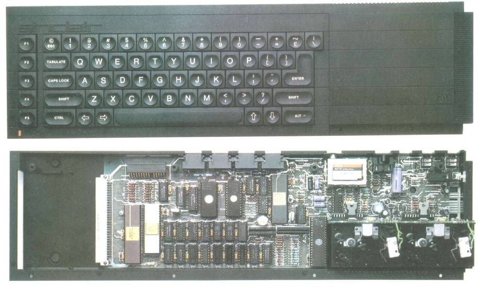
Also, my own versions of sound and other extensions will have a form factor so that they will fit inside the intended enclosure, so they will be 6 cm wide, and 10 cm long. Very much like the Sinclair QL expansion port, seen here at the bottom left, except I'm not using a DIN connector but a simple pin-header.
I will try to capture my idea in a future 3D preview of the ZX81+35.
Re: ZX81 Clone
The "unreliability" of the connection was due to very cheap connectors. This bad quality isn't available anymore.
Recent productions like zeddynet, zxram and zxpand as well as mr.x etc have no problem at all.
So changing of the connector type isn't neccessary any more.
The reason why zeddynet goes for din plugs is just because ZX96 in the 90 s had this bus type.
kind regards Paul
Recent productions like zeddynet, zxram and zxpand as well as mr.x etc have no problem at all.
So changing of the connector type isn't neccessary any more.
The reason why zeddynet goes for din plugs is just because ZX96 in the 90 s had this bus type.
kind regards Paul
In theory, there is no difference between theory and practice. But, in practice, there is.
Re: ZX81 Clone
That might all be, but for me using pinheaders is the best solution, also because its easy to align the expansion board on the same level as the main board, the 3D preview below shows exactly what I have in mind.
The "din plug" of zeddynet was not even known to me when I designed my own solution.
when I talked about the din plug, I meant the din plug of the QL.
My expansion board fits in the area left of the main board, and above the keyboard, within my own enclosure design, just like a QL expanision board fits within the open area to the left of the din plug of the QL.
Note that the expansion board can be a simple blank board that extends the pinheader to the left, and can end in an edge connector on the left side of my ZX81+35 design.
I won't change my design so that it has an edge connector, as doing so would mean that I have to use an expansion board that sits well below the level of the main ZX81+35 board, because its edge contra connector has to be mounted on top of the expansion board, and that is just plain ugly. Also as the edge connector would sit at the left it would be inconvenient to directly plug in existing boards, you would need an extender board anyway.
This is simply the neatest solution.
this preview shows the ZX81+35 from the front, so you can see that the expansion/extender board is level with the ZX81+35 main board.
and although its not drawn in this preview the left side of the expansion/extender board, used as purely an extender board, can have the edge connector you want, at a convenient location. you don't even have to design and manufacture such an extender board, as it can be crafted from a standard proto PCB that has an edge connector area, like the one in this picture: