

Congratulations, looks very good now.
Latching the video output signal could make life easier to match it more perfect with black and white or first/last pixel width.
I never saw this before in a schematic but verified only the original ZX80 schematic for this.
ZX81+35 Clone

Re: ZX81 Clone
tested my joystick interface, integral to the design, added the 5 2N7002 FETs and the DB-09 connector, and connected a joystick.
At first everything seemed to work fine, the joystick generated the keypresses 5, 6, 7, 8 and 0 like it should.
but when I tried to edit a BASIC program, I found that the arrow keys did not work, except left-arrow. So the ZX-81 did not seem to recognize correctly that I pressed shift with the keys that had FETs connected to KBA12 (12 keyboard line). at the same time rubout worked fine. I suspected the capacitive load of four gate-source parasitic capacitors has something to do with it, so I tried replacing the 2N7002 FET's with MMBT3904 transistors, and that worked great!
Luckily they are drop-in pin-compatible with the 2N7002, and I had the foresight to add a current limiting resistor to the common pin of the joystick.
I also tried loading a program from simulated cassette port, (audio output of my laptop), but it did not work, the audio signal reached the input pin of the keyboard buffer (pin 2) nearly perfect, but the load command did not recognize the signal. Its probably the program I used to convert a ZX81 .P file to an audio signal. The program is designed for a spectrum, and takes .P files, but probably does so with the idea that they are spectrum .P files, and generates a signal suitable for a spectrum, not for a ZX81. I saw a stream of 4 pulse or 8 pulse groups on my oscilloscope. Have to look for a ZX81 compatible .P file player.
Re: ZX81 Clone
One here for windows/.net:
viewtopic.php?f=11&t=20&hilit=p2wav
And another:
viewtopic.php?f=6&t=425&p=3460&hilit=wav#p3460
viewtopic.php?f=11&t=20&hilit=p2wav
And another:
viewtopic.php?f=6&t=425&p=3460&hilit=wav#p3460
Re: ZX81 Clone
You may try the attached small program (WAV file) which loads a demo with a few basic lines only with normal speed and a few seconds duration. This has a condensed display file which is expanded automatically after loading when pressing a key to show the listing. Nothing to worry about but reduces load time significantly. This works quite well on several ZX81. Important is the level of the audio signal, it has to be high enough with minimum 4 Vss I guess. I made also good experience while saving audio on WIN with Audacity, increase it's low volume to maximum amplification and discard the warnings (overload) and play it back via the sound card. My new Apple Mac mini doesn't reach enough audio volume on it's output but the Realtek sound card on WIN 7 PC does it very well. Also be sure to use mono audio cables as the stereo cables have another incompatible pin out.
- Attachments
-
- ZX81DEMO.wav.zip
- (2.77 KiB) Downloaded 186 times
Re: ZX81 Clone
thanks a lot, I will try it very soon (next Tuesday evening).PokeMon wrote:You may try the attached small program (WAV file) which loads a demo with a few basic lines only with normal speed and a few seconds duration. This has a condensed display file which is expanded automatically after loading when pressing a key to show the listing. Nothing to worry about but reduces load time significantly. This works quite well on several ZX81. Important is the level of the audio signal, it has to be high enough with minimum 4 Vss I guess. I made also good experience while saving audio on WIN with Audacity, increase it's low volume to maximum amplification and discard the warnings (overload) and play it back via the sound card. My new Apple Mac mini doesn't reach enough audio volume on it's output but the Realtek sound card on WIN 7 PC does it very well. Also be sure to use mono audio cables as the stereo cables have another incompatible pin out.
I'm not worried about stereo/mono cables, my clone uses a stereo input, but only uses the left (tip) signal. Also, I have a modified input, which is much more sensitive than a normal ZX81. While playing the converted to .wav .p files, (for the spectrum) I got a very clean signal on the binary input with a wide range of medium audio settings. directly having a test .wav file is ideal. I have also arranged for a real ZX81 to compare loading with. I remember that the ZX81 "echoed" the received cassette signal back to the sync signal, so that you had a visible loading signal, a tradition taken over by the spectrum. For a very short while I worked for a game software company, and one thing I wrote was a special "fast loader" for MSX computers that imitated the same border color bars the spectrum was so famous for. The loader also set up the MSX so it was possible to load a text editor (and other programs) written for CP/M on an MSX with just a cassette recorder. it could also load intro screens directly from cassette to MSX screen 2 screens, spectrum style.
Re: ZX81 Clone
Well - there are usually horizontal syncs present in the audio cassette signal but these are suppressed with the filter in the line 47pF/1M and 47nF/1k. This is not exactly timed on the horizontal sync (should be trimmed to 64us rather than 47us +/-5%) but is quite effective. But I did look into your schematics and found that you invert the audio signal with a transistor. This is quite problematic as I know the loader routine (worked a lot a few years ago implementing the loader into the ZX-IDE, a development tool) and your default input is high (no data) while in original ZX80 schematics this is low. So it is waiting for a high in the loader which signals an incoming bit. I am pretty sure this may confuse the loader.
Re: ZX81 Clone
yeah, I was aware that the cassette output needed filtering of the sync pulses, and so I added such a filter, but I did give the output a somewhat higher output level, so that potentially you could record it with a sound card. I listened to the output signal, and it sounded okay to me, but I have not attempted to record it yet.
I was aware that the input transistor is inverting the signal, but as each pulse consists of both a positive, and a negative going pulse (so is polarity independent, as it should be) I thought it would not matter. But you are right that the level "at rest" is now high instead of low, and that might indeed confuse the software detection. I think the issue can be simply resolved by adding a 10K pullup resistor on the base of the transistor that is just strong enough to turn the transistor on as default, but during a negative going pulse can be overridden. will try that on Thursday. it would explain why the ZX81 would not see any signal at all, and would display only a black screen.
I was aware that the input transistor is inverting the signal, but as each pulse consists of both a positive, and a negative going pulse (so is polarity independent, as it should be) I thought it would not matter. But you are right that the level "at rest" is now high instead of low, and that might indeed confuse the software detection. I think the issue can be simply resolved by adding a 10K pullup resistor on the base of the transistor that is just strong enough to turn the transistor on as default, but during a negative going pulse can be overridden. will try that on Thursday. it would explain why the ZX81 would not see any signal at all, and would display only a black screen.
Re: ZX81 Clone
Well, that was a big fiasco!
adding a pullup did not work, somehow the signal lifted the bias on the transistor, and the resulting output was still inverted. In the end, after looking at the level of the input signal I decided to remove the transistor. Instead I used this circuit:
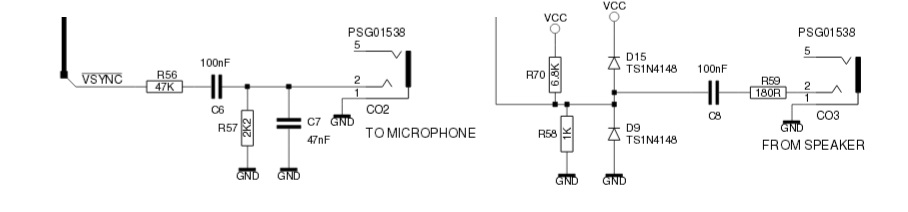
I also noticed that the pin I used ended up being the signal on the ring, not the tip, so I had exchanged left and right in both CO2 and CO3, that is what can happen if you design for a part that you do not have, so cannot check. Many datasheets for cheap parts are not worth the paper they are printed on.
But anyhow, I exchanged pin 2 and 5 in the schematic symbol, and designed the above alternative circuit, perhaps the diode network is unnecessary.
I tried to patch the above input circuit (from speaker) leaving out D9 and D15, and R70. But could not get it to work, not even with playback with PokeMon's ZX81DEMO.wav The load command started with black bars in the screen, so looked promising, but when playback started the screen went black, and stayed black.
I also tried to save, and record on the laptop with the built in sound recorder, but could get not a peep recorded. Although the (very small) signal was definitely there. I decided to increase R57 from 1K to 2K2, but it did not help. Probably there is something wrong with my recording setup, as all I got was silence, even after turning the mike input all the way up, perhaps its because the input signal ends up on the ring, not on the tip, and the software is set to record from a mono mike.
so more testing/patching is needed, but not on next weekend, because I will go to family for eastern, and I'm also a bit fed up with it being so difficult. Next week Ill do another attempt.
adding a pullup did not work, somehow the signal lifted the bias on the transistor, and the resulting output was still inverted. In the end, after looking at the level of the input signal I decided to remove the transistor. Instead I used this circuit:
I also noticed that the pin I used ended up being the signal on the ring, not the tip, so I had exchanged left and right in both CO2 and CO3, that is what can happen if you design for a part that you do not have, so cannot check. Many datasheets for cheap parts are not worth the paper they are printed on.
But anyhow, I exchanged pin 2 and 5 in the schematic symbol, and designed the above alternative circuit, perhaps the diode network is unnecessary.
I tried to patch the above input circuit (from speaker) leaving out D9 and D15, and R70. But could not get it to work, not even with playback with PokeMon's ZX81DEMO.wav The load command started with black bars in the screen, so looked promising, but when playback started the screen went black, and stayed black.
I also tried to save, and record on the laptop with the built in sound recorder, but could get not a peep recorded. Although the (very small) signal was definitely there. I decided to increase R57 from 1K to 2K2, but it did not help. Probably there is something wrong with my recording setup, as all I got was silence, even after turning the mike input all the way up, perhaps its because the input signal ends up on the ring, not on the tip, and the software is set to record from a mono mike.
so more testing/patching is needed, but not on next weekend, because I will go to family for eastern, and I'm also a bit fed up with it being so difficult. Next week Ill do another attempt.
Re: ZX81 Clone
I think the problem is the low impedance input with the 100nF capacitor. This forms an R/C combination of 100nF / 1k as a high pass filter. This would modify the incoming pulses. The bits are coded as a series of pulses (4 pulses = 0, 9 pulses = 1) while one puls has a length of 150us. This low pass has a Tau of 100us (100nF*1k) which means after 100us the signal has about 70% only. This way your input signal is quite disformed and probably no longer a valid cassette input signal. The routine is measuring the length of any pulse and this is quite modified. Additionally the asymmetric wave form would increase the effect of the r/c combination. So I would try to use a bigger capacitor here - minimum 1uF better 10uF. Or increasing your input resistors at lease by factor 10. Or a combination of both.
As Bodo (a german ZX team member) found out, the pulse length are simply added for one bit and has a tolerance to meet 0 or 1 but this tolerance is not too much (maybe 5-10% only). I think he created a way to transfer data with a simple serial port connected to the ZX81. Not sure what baud rate exactly used, this is a quite old project.
So here details for the cassette signals:
http://problemkaputt.de/zxdocs.htm#zx80 ... ttesignals
There is also a silence between every bit of 1300us which is even a bigger problem. This is a frequency part of 770Hz which is hard to pass over your input filter. So I would try both, increasing resistors by factor 10 and increasing capacitor by factor 10 to have a chance of signal passing without too much modification.
Re: ZX81 Clone
yeah, these values are mostly copied from other rebuilds, with a bit of inspiration from the ZX80, ZX81 and its clones, I think the major problem with these is that most of them use LS TTL logic, which have completely different input specs than my HCT logic. That and my suspicion is that none of the rebuilds (clones) really did manage to create a design that could input real tape signals. I suspect they fed TTL compatible pulses from a software program that outputted them through the PC's printer port, to load programs in. in fact I have seen one design that just had a resistor divider as input, and which stated as much in its documents.
Your advice that I need a larger input cap, and larger input resistors makes sense, but wIll add that I think the input also needs a low resistance (something like 220 Ohm to 1K) load resistance at the input, to keep DC balance intact after the cap in the sound output.
I could see that 100nF was too low, (due to the shape of the input pulses) and in fact I had started with 10uF initially, but most other designs used much lower capacitances, as low as 47nF (in case of the original ZX80 and ZX81, so I was lead to believe a smaller cap is better.
I noted that both the ZX80 and ZX81 used incredibly simple input designs, with small caps, which probably only worked (badly) because of the low threshold LS TTL inputs have.
I will experiment further next week
p.s. I already had the extensive document from NoCash in my possession, but thanks for pointing out it had this tidbit of info.