It lives 
- image.jpg
- A working ZXmore :-)
- (202.54 KiB) Downloaded 148 times
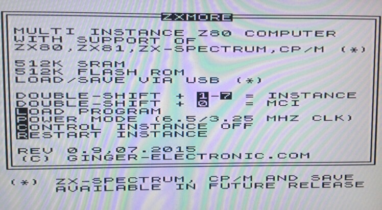
- Boot screen
- image.jpg (108.43 KiB) Viewed 3411 times
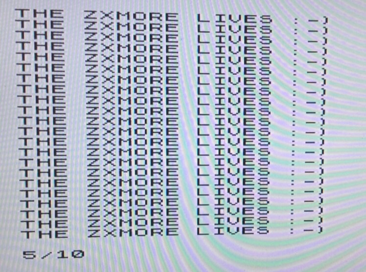
- ZX81 mode
- image.jpg (143.37 KiB) Viewed 3411 times
Ignore the coloured patterning, that's an artefact between the monitor (LCD TV) and the camera and maybe the LED lighting. Not seen this effect this bad when I have taken pictures before, so will have to try again tomorrow and see if I can work out why.
A nice kit, thanks Karl

Fitting the regulator: First I did a test fit on the underside of the board to work out where to bend the legs. A nice set of smooth flat nose pliers is great for this. Then, instead of trying to insulate the 0V/GND "via" under the regulator heatsink, instead I put a M3 machine screw through from the underside of the board. Then put a bright plated plain steel washer on the top side of the board over the threaded machine screw. Then applied solder to the edge of the washer and the PCB "track" on the regulator legs side of the washer. This then held the washer in place. The heatsink and the regulator where then fitted, and then secured with a M3 nut. Finally, after tightening the machine screw and nut, I soldered the regulator pins in place. The washer creates a nice gap so that the heatsink does not touch the"via".
Note that the machine screw supplied in the kit is a little too short for this, so I used a slightly longer one. I think I used a 6mm pan head type, but it may have been a 10mm one.
Mark