ZXmore or the ZX80CORE follow-up

Any discussions related to the creation of new hardware or software for the ZX80 or ZX81
User avatar
PokeMon
Posts: 2264
Joined: Sat Sep 17, 2011 6:48 pm

Re: ZXmore or the ZX80CORE follow-up

Post by PokeMon »

Lurch666 wrote:I had a quick look in the user manual but must have missed that bit.Will read it all now.

Changing the jumper still gives me a white screen with nothing else.With the rom switch on 0 if I press reset the screen flickers then fades to black.
If I put the rom switch to anything else the screen flickers but stays white.The LED still changes to the correct colours.


EDIT:Looked through the 1.7 user manual and still can't seem to find where it says I should use the jumper at A3 instead of A7
Too - bad.
If you try instance 1 directly you should power-off and after power-on again.
The LED colour is shown correctly but anyway there maybe situations that the LED shows correct colour but system hangs.

Do you have bridged pin 9 and 10 of IC23 ?
There is a shadow in this area but not good displayed.
Do you have isolated the via under/near the cooler of the 7805 ?
Did you measure the voltage at the chips (5V and 3.6V at D9) ?
What test equipment do you have ?

The hint with A3 is on page 12 of the V1.7 manual near the first picture.
Additionally the I/O base address has been changed so the jumper at J12 has to be moved from A7 to A3 after (!) the update completed.
You did not make the update yourself as I did already when shipping. ;)
User avatar
Lurch666
Posts: 36
Joined: Sun Nov 22, 2015 7:07 pm

Re: ZXmore or the ZX80CORE follow-up

Post by Lurch666 »

I'm powering off before making any changes so I'm changing the rom switch then powering on.
I do have pins 9 and 10 bridged with a wire so I didn't damage the traces underneath.
I have a bit of insulation tape over the via.
I have checked the voltage at a few of the 14 pin chips and they are all 5v.
D9 reads at 3.3 on one side and 4.2 at the other if I use the usb connector as negative.
I just have a multimeter.


The info about the jumper change was also mentioned earlier in this thread but it's hard to find when speed reading through a load of info (That's my excuse anyway :D )
Also found mention about the extra 47pf capacitor on pins 27 & 29 in your post about the 1.7 firmware.Could the fact I don't have one fitted (waiting for a delivery from ebay) be the problem?

Playing a bit more I have found out if I leave it on the display slows starts to deteriorate until after about 30 seconds it starts rolling unless I'm at rom switch position 0.Then I think I'm getting little or no video output at all.
User avatar
PokeMon
Posts: 2264
Joined: Sat Sep 17, 2011 6:48 pm

Re: ZXmore or the ZX80CORE follow-up

Post by PokeMon »

As you have the newest CPLD the 47pF isn't necessary anymore.
This was just a temporary solution after some conceptional change from the first delivery.
If you checked for possibly missed solder joints (as the board looks very clean) and proper set of all chips in the sockets and all chips at the right place I could deliver a new flash rom and CPLD to you to test if this solves the problems. Usually I test all programmed devices before shipping but couldn't say that I might do a mistake or forget something. I have been a bit stressed the week I posted it to you. :?

So please do a last optical check and if you confirm everything checked I will sent you these two spare parts.
User avatar
Lurch666
Posts: 36
Joined: Sun Nov 22, 2015 7:07 pm

Re: ZXmore or the ZX80CORE follow-up

Post by Lurch666 »

Thanks for the offer.
I will spend a while checking (I don't like to give up trying to fix things-that's what this hobby is all about).
If I can't find the fault could I send the board to you (I will cover postage both ways)?
Then that way you won't have to sent me stuff that might not be the problem.
User avatar
Lurch666
Posts: 36
Joined: Sun Nov 22, 2015 7:07 pm

Re: ZXmore or the ZX80CORE follow-up

Post by Lurch666 »

Well it's about time I invested in an oscilloscope so I just ordered one from Amazon.It will also help keep my collection of vintage computers working.
Any tips on what signals to test for on my ZXmore?
User avatar
1024MAK
Posts: 5529
Joined: Mon Sep 26, 2011 10:56 am
Location: Looking forward to summer in Somerset, UK...
Contact:

Re: ZXmore or the ZX80CORE follow-up

Post by 1024MAK »

If you have a logic probe (or when your 'scope arrives)...

What signals do you get on the following pins of the Z80 CPU

16 /INT
17 /NMI
18 /HALT
19 /MREQ
21 /RD
22 /WR
24 /WAIT
25 /BUSRQ
26 /RESET
27 /M1
28 /RFSH

Also see what you get on pin 6 (clock) and the address pins.
Z80 pin-out here ;-)

Mark
ZX81 Variations
ZX81 Chip Pin-outs
ZX81 Video Transistor Amp

:!: Standby alert :!:
There are four lights!
Step up to red alert. Sir, are you absolutely sure? It does mean changing the bulb :!:
Spring approaching...
User avatar
PokeMon
Posts: 2264
Joined: Sat Sep 17, 2011 6:48 pm

Re: ZXmore or the ZX80CORE follow-up

Post by PokeMon »

Lurch666 wrote: Any tips on what signals to test for on my ZXmore?
Okay - this way I can give some advises to measure.
CLK is the most important, as this is the heartbeat of any computer.
In fact I don't think it is really a CLK problem as you have some effects on screen - but you never know.
Is it a digital oscilloscope ?

Would be good to measure A15 as well. This should show some activity during picture generation repeated in 64us steps with an active part of about 40us and passive part of about 24us or longer passive parts of about 3.5ms. What you could measure as well is the data bus to see any broken signals (not going high to 5V or going low near 0V). I will give you more advises in the next days, have to take a closer look and instructions to remove chips to see what is working or not. By the way - this style you will learn much about ZXmore in detail and learn more about computers in general, I think.

This could be helpful in other projects as well. Stay tuned. 8-)

And of course there is always the option to do a factory restore / repair on my table here in case you like to do this step.
User avatar
PokeMon
Posts: 2264
Joined: Sat Sep 17, 2011 6:48 pm

Re: ZXmore or the ZX80CORE follow-up

Post by PokeMon »

Well - today I will compose a diagnostic ROM which offers several test routines which should help testing a non working ZXmore with an oscilloscope and to find possible bugs/problems. I will put some functions on instance 2-7, leave ZX81 rom in instance 1 and ZXmaster in instance 0. This way this ROM could be provided in future delivery as standard. If all works, the user can program the desired ROM's in other instance via USB himself.
User avatar
Lurch666
Posts: 36
Joined: Sun Nov 22, 2015 7:07 pm

Re: ZXmore or the ZX80CORE follow-up

Post by Lurch666 »

Go my scope today (good old Amazon next day)
I havn't used an occiloscope since school (Long time ago) so I'm not sure I got it calibrated exactly correct but here are my findings from the z80:
17 /NMI stuck high
18 /HALT low to high at 1ms intervals
19 /MREQ short and long high pulses
21 /RD stuck high
22 /WR stuck high
24 /WAIT stuck high
25 /BUSRQ stuck high
26 /RESET stuck high
28 /RFSH stuck high

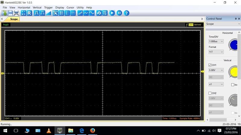
I got a Hantek 6022BE that is a unit that plugs into a usb to display the results on your monitor so I was able to grab screenshots of the more interesting outputs.

Pin 6:Clock

Image

Pin 27 /M1:

Image

and pin 30 /A0

Image

Since I'm getting pulses on A0 I'm assuming data is coming from the z80 and at least that is working.
Or am I interpreting this wrong?
User avatar
PokeMon
Posts: 2264
Joined: Sat Sep 17, 2011 6:48 pm

Re: ZXmore or the ZX80CORE follow-up

Post by PokeMon »

So /RD or /WR can not be stuck high as there is always something to read or write for the CPU. This is the main job the CPU does. Even instructions must be read first. I have a counter in the CPLD which automatically resets all registers when there is no read or write pulse for more than 16 clock cycles. This detection functions properly. By the way it does not a reset to the CPU, this is just an internal trick as I missed to wire reset to the CPLD - so it is created internal this way.

RFSH can not stuck high as well. This is always two clock cycles later than the M1 signal.
Maybe you can try to verify these signals.
One time I had an effect that CLK is present only when measuring it (a capacitive load through the scope) and stopped when not measuring it any more. So if you are able to observe to channels at the same time it maybe an option to have one channel on clock and the second on another signal to probe.

You can also measure if there is a short between RD WR RFSH to +5V (pin 11 of cpu).
Post Reply