Page 2 of 3
Re: Understanding ZX81 signals to Timex/Sinclair Printers
Posted: Fri Mar 06, 2020 8:34 pm
by 1024MAK
Can you please either upload the schematic as a non lossy compressed image format (e.g. PNG) that is not too big (dimensions) or too large (file size) or alternatively zip the file, then upload the zip.
The reason being that the forum automatically compresses jpg images to reduce their file size, but this wreaks schematic diagrams
 Mark
Mark
Re: Understanding ZX81 signals to Timex/Sinclair Printers
Posted: Fri Mar 06, 2020 8:52 pm
by XavSnap
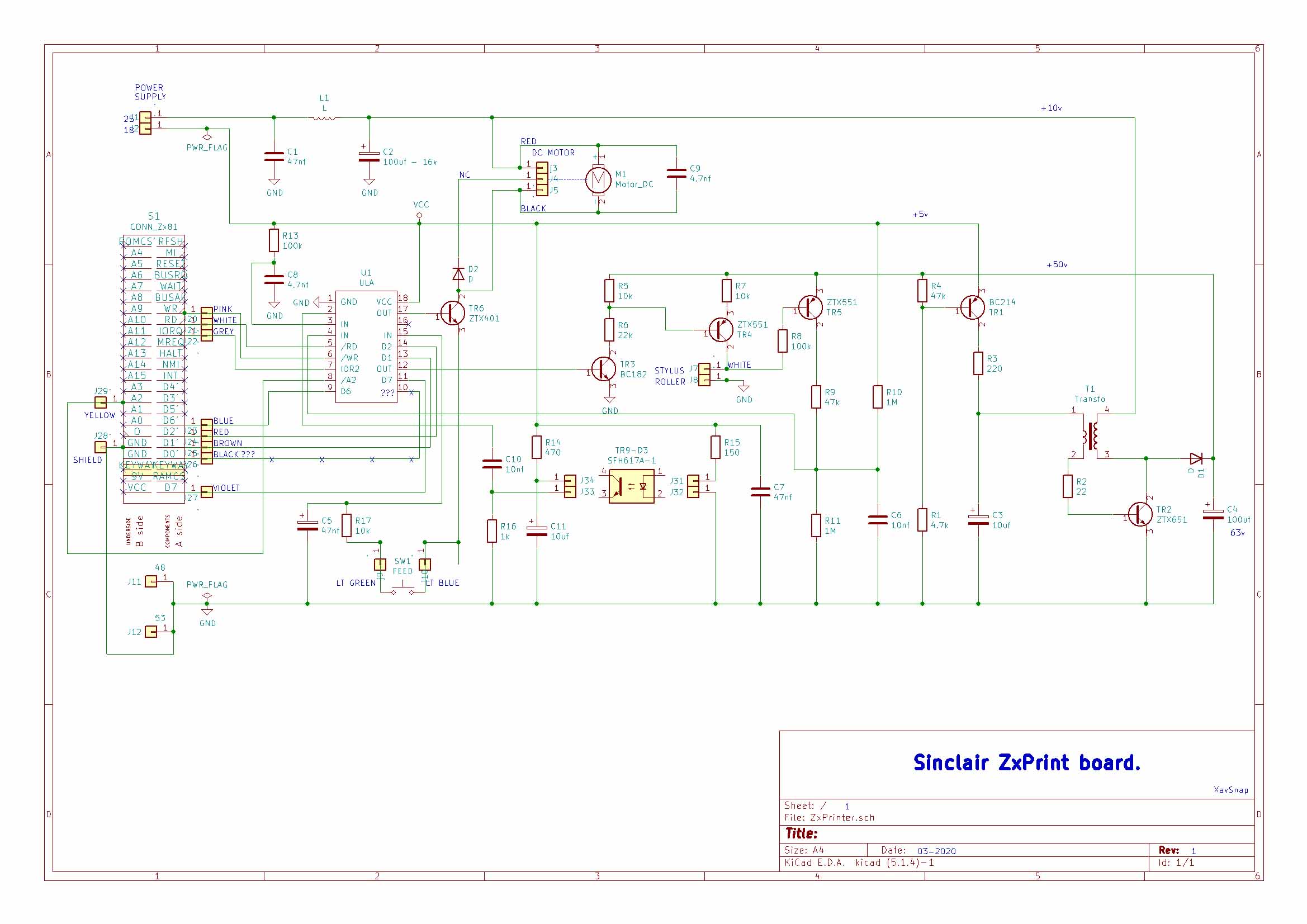
Old one : (R6 resistor ok)
Re: Understanding ZX81 signals to Timex/Sinclair Printers
Posted: Fri Mar 06, 2020 9:08 pm
by 1024MAK
I would also expect the diode D2 to connect to the +9V (+10V) rail rather than to the motor. Most small DC motors only have two electrical connections. I would expect D2 to have been provided to clamp the “back” or “reverse” EMF generated by the motor.
This is normally done by wiring a diode (reverse biased) across the motor connections. Which here are positive to the +9V (+10V) rail, and negative to transistor TR6 collector.
Mark
Re: Understanding ZX81 signals to Timex/Sinclair Printers
Posted: Fri Mar 06, 2020 9:26 pm
by XavSnap
Thanks Mark,
I had to remove a polarized capacitor too… and change the voltage converter (too big).
Re: Understanding ZX81 signals to Timex/Sinclair Printers
Posted: Sat Mar 07, 2020 9:59 am
by XavSnap
Hi,
I try to find out how the paper feed works. is there any system to gear the rotation of the paper feed roller?

Alphacom 32
Posted: Sun Sep 13, 2020 9:20 pm
by Rafael
I connected an ALPHACOM 32 to a IBM THINKPAD 760ED, Centronics port, jun 2002.
Turbo C 2, DOS.
All information available. I Don't know if it's útil.
Rafael, Bogotá, Colombia.
P.S. Excuse my poor English, pls.
Re: Understanding ZX81 signals to Timex/Sinclair Printers
Posted: Sun Sep 13, 2020 11:54 pm
by XavSnap
Re: Understanding ZX81 signals to Timex/Sinclair Printers
Posted: Tue Dec 27, 2022 6:42 am
by bwinkel67
I just got a ZX Printer and plugged it into my TS1000 and it started to smell. Took it apart and it looks like he inductor shorted. I did find a solder ball between the top leg (that bends 180 degrees and comes back down) and winding, about 3/4 of the way up...perhaps it got caught in there while sloshing around during shipping -- or something else caused it to short. Looking at the service manual, it doesn't give a value for it (I think it's the one labeled L1 at the bottom left of the diagram on page 22). It still has continuity but how do you test if it still works? It left a pretty big stink and some black suit on the big blue capacitor right next to it.
Re: Understanding ZX81 signals to Timex/Sinclair Printers
Posted: Tue Dec 27, 2022 12:48 pm
by 1024MAK
L1 is provided to limit interference on the (nominal) +9V / +10V rail. It’s value is not critical. If it has continuity, then the copper wire is okay. If this got hot, it means that there was a short circuit on the (nominal) +9V / +10V rail somewhere. A short circuit like this should show up if you use your multimeter on resistance.
Mark
Re: Understanding ZX81 signals to Timex/Sinclair Printers
Posted: Tue Dec 27, 2022 11:28 pm
by bwinkel67
1024MAK wrote: ↑Tue Dec 27, 2022 12:48 pm
L1 is provided to limit interference on the (nominal) +9V / +10V rail. It’s value is not critical. If it has continuity, then the copper wire is okay. If this got hot, it means that there was a short circuit on the (nominal) +9V / +10V rail somewhere. A short circuit like this should show up if you use your multimeter on resistance.
Thank you Mark. So I checked and found no shorts. I put it back together and this time no overheating inductor. I was able to hit the paper advance button and it moved the motor. Of course, once I tried to put the whole things carefully back together, especially gently putting the ribbon around both rollers and moving the roller caused it to disintegrate. So now I need to find a replacement for that, which was expected. I'm assuming with no overheating the problem hopefully is fixed. The only short I found was initially in the inductor where a solder blob had wedged between the coil and the top leg...so just that much of a short (maybe not quite halving the coil distance) caused it to cook...does that sound reasonable?
A couple of questions...when the inductor cooked, it spewed something out and now the two legs that hold the coil parts are loose. What was inside the coil housing? Was it glue? If I choose not to replace the inductor, since it still works, should I put a dab of glue on either side to stabilize it. Also, it seems part of the coils outer coating burned off since i can get continuity on some places of the coil to the legs (not all, but especially around where the short was). That will diminish its distance to travel...something to worry about? Should I just replace the coil? It has very little resistance, with my multimeter at 200 ohms, it reads 1.7 vs 1.3 just touching the probes together, so there is some resistance.