Cable for Adapt Electronics Speccy 48K RGB Interface

JohnM73
Posts: 8
Joined: Sun Nov 24, 2024 4:12 pm

Cable for Adapt Electronics Speccy 48K RGB Interface

Post by JohnM73 »

Hi folks.

First post here! :)

I have my original Christmas 1985 ZX Spectrum+ working well, all recapped etc. Recently I found my Grandfather's old Adapt Electronics RGB Interface in the loft, and would like to use this with my Speccy.

My monitor is a Philips CM8833 Mk2.

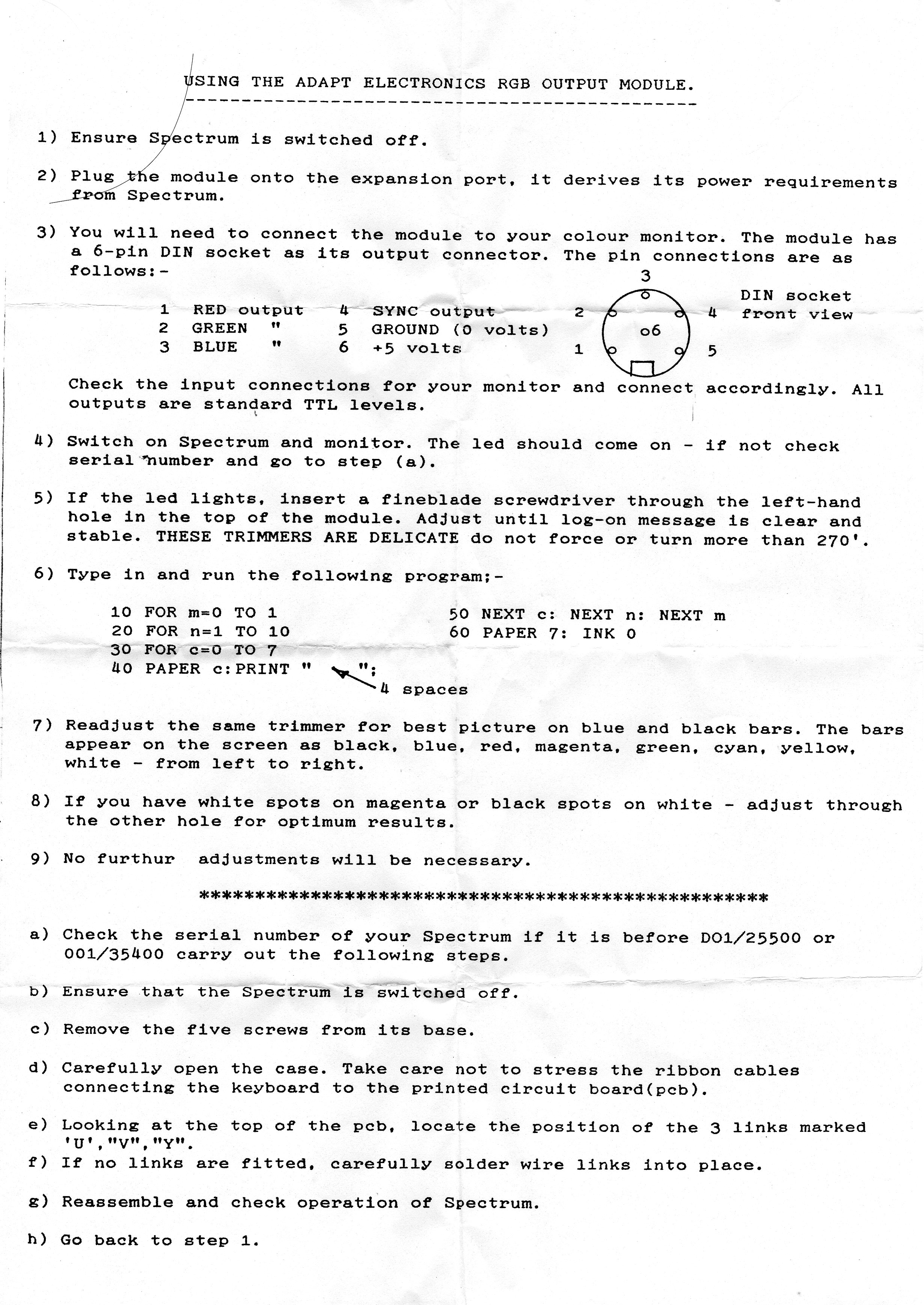
I need a cable for the interface (regrettably the original seems long gone). The link below suggests an Acorn cable would do the trick, but thought I'd check with the experts here first, as I'd like to get the best image quality for my particular monitor. Perfectly able to solder up my own cable too if somebody can tell me what goes where :)

https://retro.m1ner.co.uk/2016/03/adapt ... ut-module/

https://retro.m1ner.co.uk/wp-content/up ... -sheet.jpg

Thanks in advance,

John.
User avatar
1024MAK
Posts: 5526
Joined: Mon Sep 26, 2011 10:56 am
Location: Looking forward to summer in Somerset, UK...
Contact:

Re: Cable for Adapt Electronics Speccy 48K RGB Interface

Post by 1024MAK »

Yes, a RGB DIN to SCART cable intended for an Acorn Electron/BBC B/B+/Master should work. That’s assuming your monitor has a RGB SCART input.

If you want to make one up, use the same detail/diagram as that for an Acorn Electron/BBC B/B+/Master.

Mark
ZX81 Variations
ZX81 Chip Pin-outs
ZX81 Video Transistor Amp

:!: Standby alert :!:
There are four lights!
Step up to red alert. Sir, are you absolutely sure? It does mean changing the bulb :!:
Spring approaching...
JohnM73
Posts: 8
Joined: Sun Nov 24, 2024 4:12 pm

Re: Cable for Adapt Electronics Speccy 48K RGB Interface

Post by JohnM73 »

Thanks for your reply Mark.

Where I'm getting confused I think is in the Adapt RGB data sheet in my first post, where it says the the RGB outputs are all at TTL levels. As I understand it, TTL is a digital RGB standard? I know my Philips CM8833 Mk2 can switch between analogue and TTL RGB. So the confusion arises in do I solder up a cable for 'digital' TTL levels, or an analogue cable? And the Adapt only has a sync output (Pin 4), so would that goto H sync or V sync on the Philips? Would I need resistors on the RGB outputs to knock the levels down etc.

Found the following info. for the Philips :

---------------
TTL RGB
---------------
pin no.
1 ground
2 ground
3 red
4 green
5 blue
6 intesnsity
7 n/a
8 h.sync
9 v.sync
_______
\ . . . . ./ 5 4 3 2 1
\ . . . ./ 9 8 7 6

-------------------
Analog rgb
--------------------
1 ground
2 ground
3 red
4 green
5 blue
6 n/a
7 composite sync
8 n/a
9 n/a

I'm thinking I'm likely out of my depth here so perhaps probably best if I ask Cool Novelties or similar if they're abed to make up a cable, unless I'm over-complicating this ;)

John.
User avatar
1024MAK
Posts: 5526
Joined: Mon Sep 26, 2011 10:56 am
Location: Looking forward to summer in Somerset, UK...
Contact:

Re: Cable for Adapt Electronics Speccy 48K RGB Interface

Post by 1024MAK »

Okay, let's start with some extra information.

The Acorn Electron/BBC B/B+/Master all also have TTL RGB outputs.

A computer (expansion/interface/other device) that has TTL level RGB outputs can drive a display that has analogue RGB inputs if these inputs in the display are terminated (each input line has a resistor of around 75 ohms to 0V/GND) and a suitable resistor is wired in series between each TTL signal output and each input of the display.

The equivalent circuit is a potential divider which converts the TTL level output voltage down to no more than the maximum analogue level voltage.

If a display has TTL level inputs, TTL outputs can be connected directly.

HS or H sync is just the horizontal sync signal.
VS or V sync is just the vertical sync signal.

A "sync' output typically means 'combined' sync (also sometimes called composite sync) which is the horizontal sync signal and the vertical sync signal combined.

Some displays will work okay if the combined sync signal is fed to either the vertical sync signal input, or the horizontal sync signal or to both.

Off the top of my head, I'm unsure about the Philips CM8833 Mk2. However, I would try connecting the sync to both the H and V sync inputs. - see my next post.

Mark
ZX81 Variations
ZX81 Chip Pin-outs
ZX81 Video Transistor Amp

:!: Standby alert :!:
There are four lights!
Step up to red alert. Sir, are you absolutely sure? It does mean changing the bulb :!:
Spring approaching...
JohnM73
Posts: 8
Joined: Sun Nov 24, 2024 4:12 pm

Re: Cable for Adapt Electronics Speccy 48K RGB Interface

Post by JohnM73 »

Thanks for your explanations of RGB and TTL Mark - very helpful indeed! Copied for future reference.

Looks like I can make up a simple 6-pin DIN to 9-pin D-Sub cable then, using the Philips' D-sub input socket switched to TTL RGB mode.

By the look of it then, I might need to experiment with connecting the RGB Interface's single Sync pin to the and H-sync and V-Sync (TTL monitor end) of the cable a little.

The Philips does actually have a single Composite Sync pin on it's 9-pin D-sub input, but that is only when switched to analogue mode. Whereas the Adapt RGB Interface only has the one sync output.

I'll try joining the H and V sync at the Monitor end of the cable and see if that works, then to just the H sync, and the V sync, and see which gives the best results.

Ta.
User avatar
1024MAK
Posts: 5526
Joined: Mon Sep 26, 2011 10:56 am
Location: Looking forward to summer in Somerset, UK...
Contact:

Re: Cable for Adapt Electronics Speccy 48K RGB Interface

Post by 1024MAK »

Having looked at the service manual for the Philips CM8833 Mk2, the sync signal only needs to go to either pin 8 (H sync) or pin 9 (V sync). There is no need to connect to both, as internally both pin 8 and pin 9 signals are combined anyway.

Mark
ZX81 Variations
ZX81 Chip Pin-outs
ZX81 Video Transistor Amp

:!: Standby alert :!:
There are four lights!
Step up to red alert. Sir, are you absolutely sure? It does mean changing the bulb :!:
Spring approaching...
JohnM73
Posts: 8
Joined: Sun Nov 24, 2024 4:12 pm

Re: Cable for Adapt Electronics Speccy 48K RGB Interface

Post by JohnM73 »

That's great to know - makes it a simpler wiring job then! :)

Very much appreciate your help Mark, ta. Hopefully will be able to post a photo of it working within the week, touch wood!

John.
JohnM73
Posts: 8
Joined: Sun Nov 24, 2024 4:12 pm

Re: Cable for Adapt Electronics Speccy 48K RGB Interface

Post by JohnM73 »

P.S. (There had to be a p.s.) Do I need to connect the 5V pin (pin 6 on the rgb interface side) to the cable? Cursory reading about BBC computer RGB cables suggests most leave that unconnected as seldom used?

Lastly, re. the outer braided cable shielding. Shall I simply use that as the OV ground per connector, or just connect the outer shield to the DIN connector, and the DB9 connectors outer housings? Thanks.
User avatar
1024MAK
Posts: 5526
Joined: Mon Sep 26, 2011 10:56 am
Location: Looking forward to summer in Somerset, UK...
Contact:

Re: Cable for Adapt Electronics Speccy 48K RGB Interface

Post by 1024MAK »

Leave DIN pin 6, +5V unconnected. A +5V is not needed for anything (assuming there is no need for a voltage to feed the intensity input on the monitor).

If the cable has enough wires, one can be used as The 0V/GND. Then connect the shield/screen of the cable at one end only. Ideally at the monitor end.

Alternatively, the shield/screen can be used as the 0V/GND, with connections at both ends.

The ZX Spectrum doesn't have a separate chassis/ground. If the DIN socket does have it's shield connected, it will be to the 0V/GND.

Mark
ZX81 Variations
ZX81 Chip Pin-outs
ZX81 Video Transistor Amp

:!: Standby alert :!:
There are four lights!
Step up to red alert. Sir, are you absolutely sure? It does mean changing the bulb :!:
Spring approaching...
JohnM73
Posts: 8
Joined: Sun Nov 24, 2024 4:12 pm

Re: Cable for Adapt Electronics Speccy 48K RGB Interface

Post by JohnM73 »

Brilliant, thanks again (again!) Mark.

Will leave the 5V unconnected then, but will keep a spare unconnected wire free just incase (10 wires in this shielded cable so a few spare).

Will do as you suggest and connect the screen at the Philips monitor end only then (shield of the RGB input socket connected to mains earth via pcb tracks in the monitor I believe).

Ta.
Post Reply