PhilD wrote: ↑Sun Jun 07, 2020 10:14 amDoes this help?
So the extra component that connects to the extra connection going to the modulator appears to be a 10nF ceramic capacitor. One end connects to the 0V/GND of the existing capacitor C42. Further, it looks just like some of the other 10nF ceramic capacitors that are fitted to the board. Therefore it could well be possible that your machine was manufactured like this. Or it was modified by the manufacturing company prior to being shipped to New Zealand.
Doing some searching, the New Zealand analogue TV broadcasting used PAL B/G and transmitted on VHF and UHF. So it’s hard to say what frequency/channel the modulator on your ZX Spectrum was designed for.
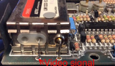
In any case, in order to carry out a composite video modification, ignore this extra circuitry. Desolder the video signal wire going to the modulator, gently pull out of the PCB (if it does not pull out easily, the solder has not melted enough, don’t force it or you will rip off the PCB tracks and the plated through hole). Do the same with the +5V power lead (the right hand wire going into the modulator).
Then carry out the composite video modification as normal. I do strongly recommend you use a 100uF 16V electrolytic capacitor so that there is DC isolation of the video signal. The negative lead of the capacitor goes to the TV. The other capacitor lead goes to the PCB pad marked video signal in my photo:

- ZX Spectrum 48K Modulator video signal
Oh, by the way, the ULA that is fitted is a PAL 50Hz/15625Hz 625 line version (type 6C001E-6) and is the type normally seen in issue 3 boards, so this is a late issue two board. The date code of your issue two board is week 20 in 1983, the 4116 ‘lower RAM’ chips are week 23 in 1983 and the ULA is week 26 in 1983 (late June/early July 1983).
Mark